This thread has been locked.

If you have a related question, please click the "Ask a related question" button in the top right corner. The newly created question will be automatically linked to this question.

IWR6843AOP: configuration help

Part Number: IWR6843AOP
Other Parts Discussed in Thread: IWR6843, , IWR6843ISK, AWR1443, AWR6843, IWR1443

I'm trying to use the IWR6843AOP in an application where I'd like to detect a 500mm (w) x 250mm (h) obstacle at a distance of up to 20m when moving at 40kph. The radar will be mounted to a vehicle moving up to 40kph; the objects being detected are stationary.

I'm using the mmWave Sensing Estimator, v1.4, to generate a config file and I had a couple questions.  First of all, it seems there's no input parameter for the antenna being used, which I'm a little confused about. I've seen other posts on this forum where people were directed to use the sensing estimator tool with the AOP unit, but in the drop-down for selecting the senor only the IWR6843 (not AOP) is available, so I'm assuming it's ok to use that one? But then how are the different antenna characteristics taken into account between the AOP and IWR6843 EVM (which comes in both narrow and wide FOV options)?

Here's the parameters I was thinking of using to get started:

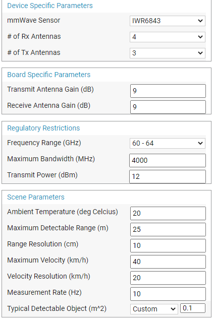
* Is there any rule of thumb for setting range resolution compared to minimum detectable object size? For example in my case I figured a value of 10cm, which is a little less than half of the minimum dimension I'm trying to detect of 25cm, seemed reasonable. But I'm not sure if having higher resolution and thus more 'samples' where the object is detected is desirable? Or is there also a tradeoff to consider where setting the resolution too low will result in more spurious noise in the point cloud?

* What impact does the 'Typical Detectable Object' parameter have? It doesn't seem to actually change any of the chirp parameters. Is it just for reference?

* How should I be thinking about velocity resolution in my application, where the radar is moving but the objects I'm trying to detect are stationary? Is it irrelevant since there's no difference in velocity between the objects I'm trying to detect?

thanks in advance,

Ryan

  • Hello

    You assumption about being able to use the chirp on interchangeably between IWR6843ISK and IWR6843AOPEVM is right in general.

    Ranges may vary based on Antenna gain adjustments.

    Have you had a chance to look at the mmWave training video to establish a connection between FMCW chirp parameters and sensing needs.

    https://training.ti.com/mmwave-training-series

    Thank you,

    Vaibhav

  • Ryan,

       In the mmWave sensing estimator for changing the Antenna parameter, you could use the Antenna gain (Tx antenna gain/ Ra Antenna gain). 

    For different hardware Antenna gains are different and also customer could choose to develop custom antenna with different gain configuration based on their application choice, 

    You could refer to below Antenna database in the the below resource explorer. 

    https://dev.ti.com/tirex/explore/node?node=AKu-aTm5FIcxlwZJU1pLBw__VLyFKFf__LATEST 

    Below link provides Antenna gain for the AOP chip. 

    https://dev.ti.com/tirex/explore/node?node=AGMzFzzFdFllMlyaWeXNlw__VLyFKFf__LATEST

    You could select IWR6843 device from the drop down menu and plug in Antenna gain from the Antenna database for a given device. Most of the Tx and Rx antennas are identical hence you could use same antenna gain for Tx and Rx. 

    As you may have noticed from the above mmWave training range resolution is dependent upon the RF bandwidth, By increasing RF bandwidth you could get up to 4 cm range resolution. But at 20meters distance such high resolution may not be needed, you may want to optimize this parameter. Higher the range resolution, more samples, memory, MIPS involved, for each point Range, velocity, angle need to be estimated, There is computational over-head  and this may limit the maximum refresh rate that you could achieve. 

    Detectable object size is mainly governed by the Radar cross section also known as RCS. And it varies based on the size, shape, type of objects, a rough guiding values have been given in the sensing estimator.  It's independent of chip parameter. 

    The phase difference measured across two consecutive chirps can be used to estimate the velocity of the object. Higher velocity estimation requires closely spaced chirps. 

    Velocity estimation relies on the relative speed difference between the Radar and object. It doesn't matter either object or Radar is stationary as long as one of them is under motion, it measure the relative velocity between Radar and object. 

    You could refer to the below training module from the above link

    https://training.ti.com/intro-mmwave-sensing-fmcw-radars-module-3-velocity-estimation?context=1128486-1139153-1128544 

    Also you could refer to 36 page of the training manual for the velocity estimation. 

    https://training.ti.com/sites/default/files/docs/mmwaveSensing-FMCW-offlineviewing_2.pdf

    Thanks and regards,

    CHETHAN KUMAR Y.B.

  • Hi Chethan,

    Thanks for your response. I've had the chance to dig a little deeper into the training modules and also did some side-by-side comparisons using the Sensing Estimator to get more of a handle on the impact of input parameters on the outputs. I've got a few more questions for you based on what I've seen:

    First of all, I noticed that increasing the Range Resolution input improves the output in “Detectable Object Range” and I’m finding that non-intuitive.

    For example, with my object size being as small as 20cm, I assumed it’d be best to set the Range Resolution input as low as I could without getting any errors. In my case, that was 8cm, and gave me a ‘Max Range for Typical Detectable Object’ of 23.65m, and a ‘Min RCS Detectable at Max Range’ of 0.05m^2.

    But then, if I increase Range Resolution to 20cm, the output parameters improve to ‘Max Range for Typical Detectable Object’ of 24.99m, and a ‘Min RCS Detectable at Max Range’ of 0.04m^2.

    Why would a larger range resolution allow for detecting a smaller RCS at an even greater distance?


    Secondly, I used the Sensing Estimator to do a comparison between IWR6843 and AWR1443, using all of the same input parameters other than Frequency range (60-64 for the IWR and 77-81 for the AWR). So BW is the same, only difference is higher frequency.

    Interestingly enough, the IWR gave better results:

    Max Range for Typical Detectable Object’ of 24.99m, and a ‘Min RCS Detectable at Max Range’ of 0.04m^2, versus the AWR which gave Max Range for Typical Detectable Object’ of 20.51m, and a ‘Min RCS Detectable at Max Range’ of 0.09m^2.

    I would have expected the higher frequency band to give better results, since:

    a)      Range resolution should be dependent on bandwidth, which is the same (4GHz) in both cases

    b)     Velocity resolution should get better with smaller wavelength (i.e. higher frequency)

    c)      SNR should get smaller with higher frequency

    So where is the mismatch coming from, between what the theory suggests and what the estimator is giving?

    I also wanted to ask about the different antenna gain inputs in the Sensing Estimator. I’ve currently got an IWR6843AOP and AWR1443, so those are the two I’ve been looking at. The Antenna Database sub-menu in the ‘Automotive Toolbox’ (following the link you directed me to) seems to be pretty incomplete, only showing the AWR6843; so for the AWR1443 can I instead use the figure listed under the IWR1443 - 9dBi for antenna peak gain? And would I then enter that value in the Sensing Estimator tool for both Transmit and Receive Antenna Gains?

    As for the ‘Transmit Power (dBm)’ input, should I use the typical specified Transmitter ‘Output power’ from the RF specification section of the chip datasheet? So 12dBm for the AWR1443, and 15dBm for the IWR6843AOP (named differently on that datasheet as ‘Single transmitter output power EIRP)?

    Finally, I’ve just come across the relatively new ‘cascaded’ option you have (https://www.ti.com/tool/MMWCAS-RF-EVM) and I’m wondering if you can comment on its merits in my specific use case?

    thanks in advance,

    Ryan


  • Ryan,

        Acknowledged, I may need couple of days to respond to your message. 

    Thanks and regards,

    CHETHAN KUMAR Y.B. 

  • Ryan,

        For the above questions: 

    Query 1: First of all, I noticed that increasing the Range Resolution input improves the output in “Detectable Object Range” and I’m finding that non-intuitive.

    Could you please provide all the input fields (Screen shot of all the fields would be helpful). Need to check in more detail to explain. Most likely increasing the range-resolution is also increasing chirp time which might increase total active time.


    Query 2: Higher RF frequency (77GHz vs 60GHz)=> smaller wavelength  => lesser max distance. Look at dmax equation on slide 50 of

      https://training.ti.com/sites/default/files/docs/mmwaveSensing-FMCW-offlineviewing_0.pdf

    For the cascaded option https://www.ti.com/tool/MMWCAS-RF-EVM  recommend to raise a new post so that it would be helpful to others as well. 

    Thanks and regards,

    CHETHAN KUMAR Y.B.

  • Please see config screenshots below:

    8cm resolution:

    20cm resolution:

    It does look like the 'Active frame time' increases slightly with the 20cm config.

    How should this tradeoff be approached in terms of larger resolution improving chirp characteristics? I.e., should the resolution be set as high as possible as long as it's less than or equal to the smallest dimension of the RCS?

  • Ryan,

      Higher active frame time will to improve over all SNR which translates to improving the distance for the same  detection threshold.  Yes, that’s a better trade off, i.e.  resolution should be set as high as possible.

    Thanks and regards,

    CHETHAN KUMAR Y.B.