


Hi Expert,
Customer is looking for fan PWM controller with fan speed monitor. We are proposing LM63 and have some questions.
1. can it control fan speed from SMBus directly instead of reading from remote diode?
2. since they already have many thermal sensors in the system, can they don't use remote diode connected to the D+/D-? how should we connect D+/D- if it's not used?
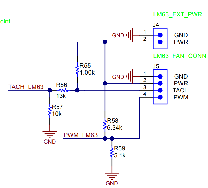
3. what's the purpose and design rules for R55, R56, R57 in the EVM circuit?
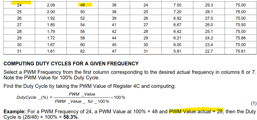
4. how does "PWM value actual=28" in the example came from?
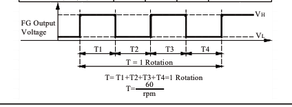
5. RPM
A. from the FAN spec, 2 pulses equal to 1 revolution. Does that corresponding our datasheet formula (2) "f"=1?
B. if Fan spec and our chip definition is different, how to convert the formula?
customer FAN spec:
LM63:

Thanks,
Allan
