This thread has been locked.

If you have a related question, please click the "Ask a related question" button in the top right corner. The newly created question will be automatically linked to this question.

TDC1000: Trigger signal to START pulse delay longer than expected

Part Number: TDC1000
Other Parts Discussed in Thread: BOOSTXL-TUSS4470, TUSS4470, TDC1011,

Hello,

I'm trying to use the TDC1000 in a fluid (liquid) identification scenario. I'm still in the early stages of development where I'm trying to make sure I'm configuring and controlling the TDC1000 properly and checking for transducer signals on my oscilloscope. The transducer I'm using is the one recommended by TI for liquid applications (www.steminc.com/.../piezoceramic-disc-10x2mm-r-215-khz-wireleads-smd10t2r111wl). I'm controlling the TDC1000 with a PIC16F18446 operating at 16MHz and outputting a clock signal to the TDC1000 at 8MHz.

So the problem I'm having is that the time between the TRIGGER signal generated by the PIC and the START pulse generated by the TDC1000 is almost one order of magnitude higher than what the datasheet says. See the photo below.

All the registers are configured in their default state, except the Config_0 register which is set as 0x44. I only changed that one as a first step to make sure I can properly configure the TDC1000 through the PIC.

Can anyone help with why that could be happening?

It might not sound like a big deal but I'm also not getting an echo signal back, so I'm wondering if these problems are related in any way. I'm trying to tackle one issue at a time. :)

Any help will be much appreciated.

Thank you,

Theodore

  • Hi Theodore,

    The time between the TRIGGER pulse and START pulse is determined as described in the datasheet:

    "During resynchronization, the trigger and START edges are aligned to the negative edge of the external clock. The time between trigger and START is equal to 3 T0 periods plus 2 or 3 T1 periods, depending on the phase between the received trigger pulse and the external clock. For example, if ƒCLKIN = 8 MHz and TX_FREQ_DIV = 0h2 (divide-by-8), the period T0 is 125 ns and the period T1 is 1 μs, resulting in a time of 2.375 μs or 3.375 μs between the received trigger signal and the generated START pulse."

    Can you also probe and plot the clock signal with your oscilloscope plot for reference?

    I personally do not have much experience with the SMD10T2R111WL transducer, but I see it described as having a "Resonant frequency fr: 215 KHz±5 KHz on Radial Mode & 1 MHz ±5 % on Thickness Mode." The reason why you may not be seeing results is that the transducer may require a center frequency of 215kHz rather than 1MHz for your use-case and mounting configuration. The transducer we typically recommend for a liquid level or concentration measurement application is the SMD15T21R111WL, which is discussed in the How to Mount it in Ultrasonic Sensing for Level Measurement and Fluid ID using TI’s TDC1000 document from Steminc.

    Alternatively, the newer TUSS4470 is also available for compatibility with transducers operating up to 1MHz for liquid coupled applications. See the BOOSTXL-TUSS4470 EVM for evaluation purposes. 

    Also, since your application only requires fluid identification, you can use the single channel TDC1011 in your final solution, or switch to the TUSS4470. You can see a comparison of the two in a liquid coupled setting at the end of the Logarithmic Amplifier for Ultrasonic Sensor Signal Conditioning app note.

    What is the size of the container you are measuring through and what is the transmission medium (specific liquid)? With some of these specs, we'll have a better idea what time-of-flight results to look for in your plots. By the way, are you using the TDC1000-C2000EVM or custom hardware for these tests?

  • Hi Akeem,

    I appreciate the quick and detailed reply.

    I'll start by numbering and addressing your comments one at a time so it's easy to keep track as we're expanding our conversation.

    1) Regarding the time between TRIGGER and START pulses, I actually tried to reproduce the exact case described in the datasheet (referenced in your reply). So my fCLKIN = 8MHz as I said earlier, which means that I should expect to see 2.375 μs or 3.375 μs. However, based on that oscilloscope photo it's around 28μs which is a significant difference. 

    2)You're right, I should have provided you with the fCLKIN plot as well. Please find it at the end of my reply.

    3) I decided to use the SMD10T2R111WL since it was the first on the TI list of tested transducers for this kind of application (www.ti.com/.../snaa266a.pdf. I'm operating it on thickness mode. But since you have more experience with and suggest the SMD15T21R111WL, I'll order it and give it a try.

    4) I'll keep both the TUSS4470 and the TDC1011 in mind for future use, but for now, I'd like to make one change at a time, so I'll stick to testing the SMD15T21R111WL with my current setup.

    5) My container is made of 1/4 inch thick polycarbonate walls and has a square cross-section. The inner distance from wall to wall is 3 inches, so the total thickness of the container is 3.5 inches. (1/4" + 3" + 1/4").

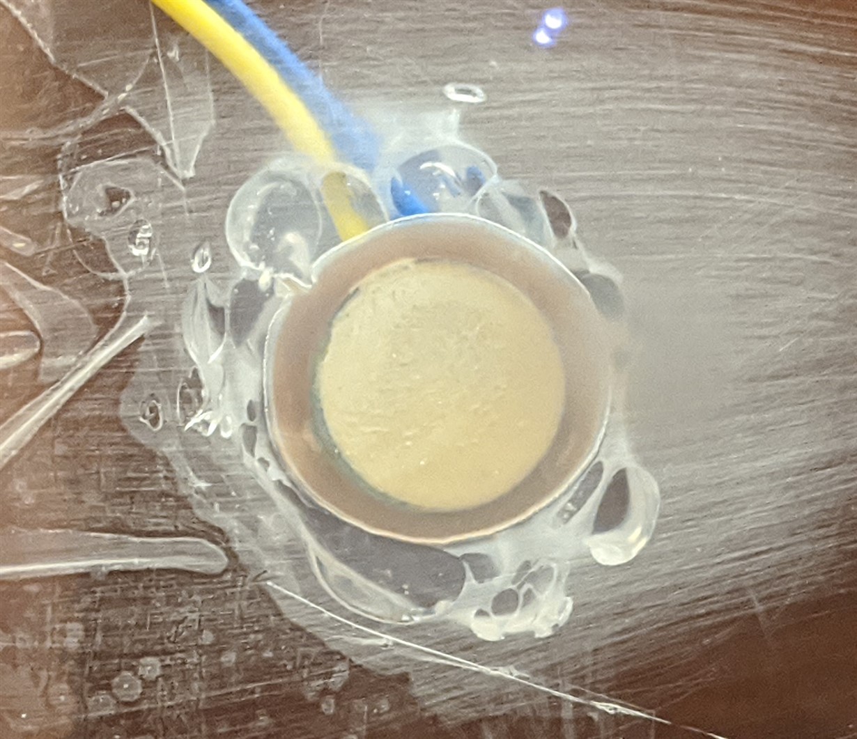
    The transducer was mounted as described in the document referenced above. Please find a picture below. The liquid for now is water. I want to prove the method works with my test setup and then I'll move on to different fluids. Let's not worry about the end application at the moment. I don't want to overload this post with too much information.

    6) As I mentioned in the first post, I'm using the TDC1000 connected to a PIC16f18446 microcontroller and I have already established successful communication between them since I managed to read all of the registers and also modify the Config_0 register to change the excitation pulses to 4 as seen in the photo. So that part is working as expected.

    Thanks,

    Theodore

  • Hi Theodore,

    Let's see if the SMD15T21R111WL transducer part number makes a difference in performance.

    In general, mounting a transducer to the exterior wall of a container tends to create the most difficult coupling situation, especially when the wall is thick. The problem relates to acoustic impedance mismatch. If the mismatch between the wall and the liquid is significant, the majority of the ultrasonic energy will either only penetrate through the wall one way, or resonate within the thickness of the wall itself.

    Be sure that there is liquid in the container, otherwise, the mismatch between the enclosure material and air will likely result in an invalid measurement. Considering communication between your PIC MCU and the TDC1000 device is working, your debug will primarily concern the mechanics of mounting the transducer. As noted in the SNAA266 app report, the best option is to create a transducer receptacle such that the transducer face is directly exposed to the liquid, which removes the acoustic impedance mismatch problem created by the enclosure's wall material and thickness.

    Unfortunately, the TI team still does not have much experience optimizing the mounting of a transducer to the exterior of an enclosure. You may need to seek guidance from the transducer manufacturer for additional mounting/debug tips.

  • Hi Akeem,

    The SMD15T21R111WL  is on its way so I'll be testing it as soon as it gets here.

    In the meantime, I found an HDPE container with thin walls (thinner than 1/8") and mounted the second identical transducer I had (they come in pairs from the manufacturer). There was unfortunately no change in behavior even though this is the same material used in the TI application report. I still can't get an echo reading of any sort on the oscilloscope. Also, of course I'm taking all my measurements with the container filled with water.

    And yes, since the circuit part of my setup is working, I agree that this is mostly a matter of picking the right transducer and mounting it properly. I will also reach out to the manufacturer to ask for assistance on this matter. For my application, there is no way around mounting the transducer on the outside of the container walls.

    However, we've kind of steered away from the original question on the delay between the TRIGGER and START pulses. Any insight on why that could be happening? I know it might not sound like much, but it's still an inconsistency I don't understand and I want to make sure this is not an underlying cause of a bigger problem with my setup.

    Thanks,

    Theodore

  • Hi Theodore,

    Returning back to the original question about the TRIGGER to START pulse delay:

    This is an interesting phenomena. You are correct that your delay time should be ~3us and not ~30us.The only variable I am aware of that affects the TRIGGER signal to START pulse delay with this much significance is the CLOCK_IN frequency. (which you have already verified).

    A few debug experiments to try:

    • Use the "Short TOF Measurement" mode instead of the "Standard TOF Measurement" to see if the TRIGGER to START delay changes.
    • Increase the pulse width of the TRIGGER signal to a larger value, like 10us.
    • Change the TRIG_EDGE_POLARITY to the falling edge.

  • Hi Akeem,

    Thanks for giving me those troubleshooting suggestions. 

    I wanted to check in and let you know that I'll be testing all of them, including the new sensor that just came in. I just got a little sidetracked with another project so I'll need a few extra days. 

    So I'm making sure the post remains active till then.

    I appreciate your help.

    Regards,

    Theodore  Koukoravas

  • Hi Akeem,

    I finally got the chance to go back to troubleshooting my ultrasound setup and I have some good news to report.

    I started by increasing the TRIGGER pulse width to 10 us and then switched to the falling edge TRIG_EDGE_POLARITY, but neither of the two worked.

    It turns out that using the default register settings made the device operate in "Short TOF Measurement" mode, so I had to switch to the "Standard TOF Measurement" instead. And that's what did the trick! I maintained the falling edge TRIG_EDGE_POLARITY and 10 us TRIGGER pulse and now my delay is between 3 and 4 us.

    I also got the chance to try the new sensor (SMD15T21R111WL) and had some promising results. I actually now get an echo response back and based on some back-of-the-envelope calculations it seems accurate. I mounted the sensor on the outside of a commercially available isopropyl alcohol HDPE container that has very thin walls.

    I'm attaching two photos below describing two different situations:

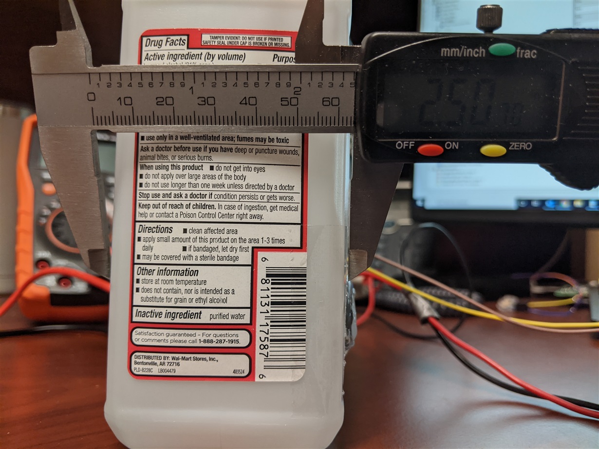
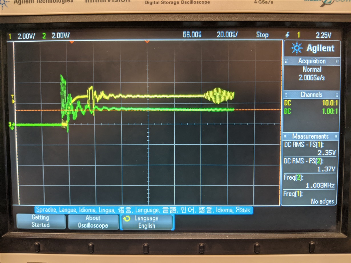
    1) Photo 1a shows the sensor mounted on the side of the container sitting upright and the approximate outer dimension of the container in inches. Photo 1b is the response I get on the oscilloscope. The bottle is almost full of IPA so in this position the TOF is expected to correspond to approximately the outer dimension of the container. Based on the speed of sound in IPA, and the size of the container this echo response looks right to me.

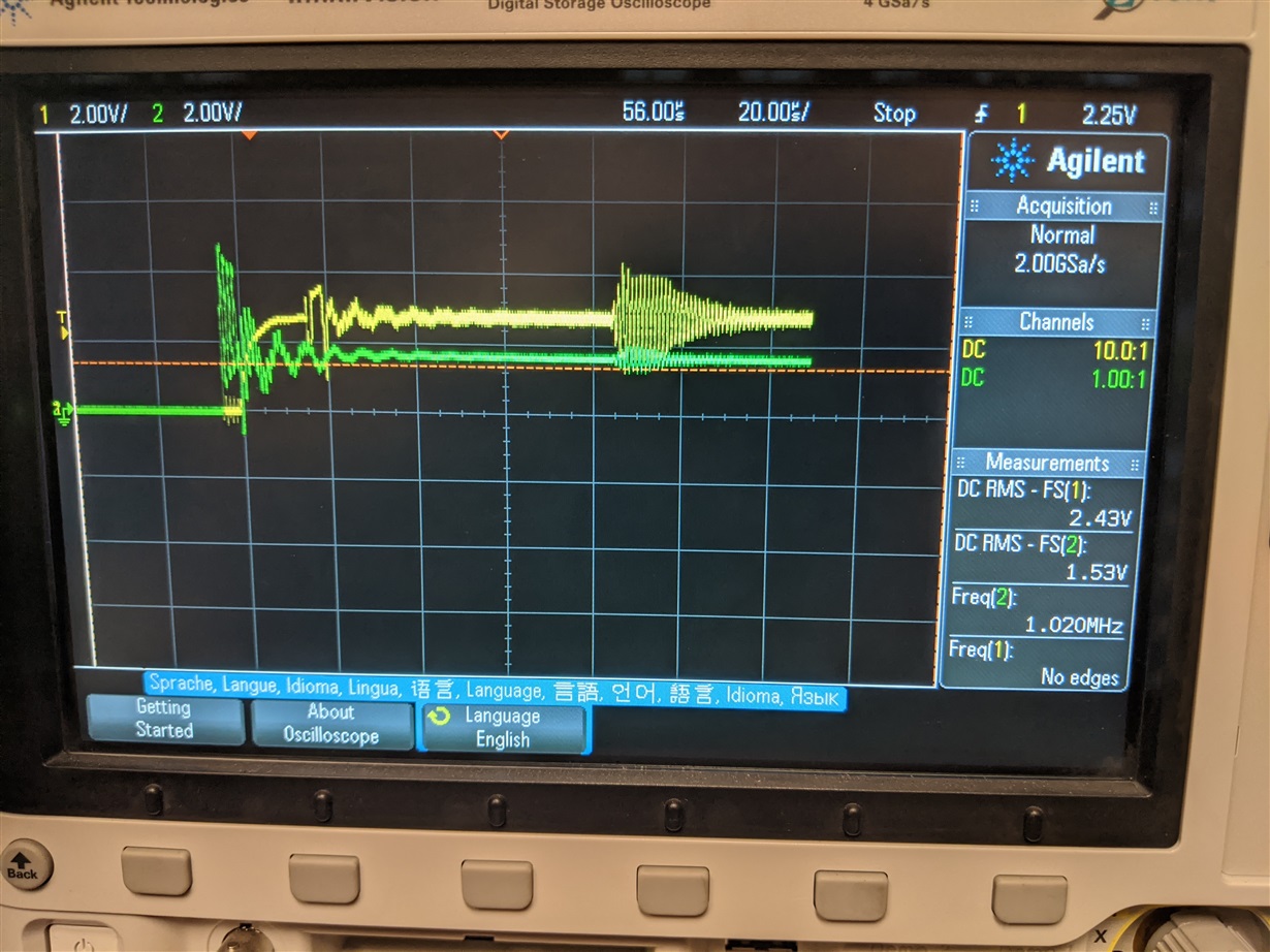
    2) Photo 2a shows the container in a horizontal position where you can see the level of IPA is now the boundary between IPA and Air that my echo came from. So in this case my echo should come a little earlier than case (1), which is what is actually shown on the oscilloscope in photo 2b.

    Overall this seems to be working fine for the time being with the SMD15T21R111WL. I appreciate your help Akeem!

    Thanks,

    Theodore

    1a

    1b

    2a

    2b