Because of the Thanksgiving holiday in the U.S., TI E2E™ design support forum responses may be delayed from November 25 through December 2. Thank you for your patience.

This thread has been locked.

If you have a related question, please click the "Ask a related question" button in the top right corner. The newly created question will be automatically linked to this question.

TDC1000-C2000EVM: Problem with 1 Mhz ultrasonic sensor interfacing and TDC1000-C200 Graph

Part Number: TDC1000-C2000EVM
Other Parts Discussed in Thread: TDC1000

Hi, I'm using this TDC1000-C200 board for water flow measurement.

I've interfaced the sensor with the TDC1000-C200 board but the GUI showing a random graph, even when the sensors are not interfaced. We set MODE 2 for our measurement

How would I know that sensors are working or not? (Sensor - Jiaking Instrument Ceramic Ultrasonic sensor 1Mhz)

also, Is there any pre-made register configuration for TDC 1000-C200 to measure flow?

PFA

I'm using this configuration but getting random values, so can someone help me out by shedding some light on this?

  • Hello,

    Do you see a stable graph when using one transducer with the default GUI settings (mode 0)?

    First, I would make sure the default TDC1000 setup works with each of your transducers, then have a look at section 2.2 of the TDC1000 FAQ to learn about the different settings and how to customize them for your application. If you still have any issues or questions then I'll be happy to help you debug it.

    Regards,

    Gabriel

  • Hello Gabriel,

    Thanks for your reply.

    I have one doubt about the default settings mentioned in the TDC1000-C2000 user's guide.

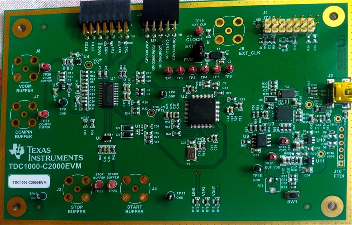
    I can't find CLK-INT on EVM.

  • CLK-INT is short for internal clock. I see in your picture the jumper is placed in this default position already (EVM ). If you were to use an external clock then you would move the jumper to the EXT position. The external clock signal would come through the SMA  next to TP19. 

    Regards,

    Gabriel