This thread has been locked.

If you have a related question, please click the "Ask a related question" button in the top right corner. The newly created question will be automatically linked to this question.

AWR1642BOOST: Bringing metal objects close to the antenna array

Part Number: AWR1642BOOST
Other Parts Discussed in Thread: AWR1642

Hi,

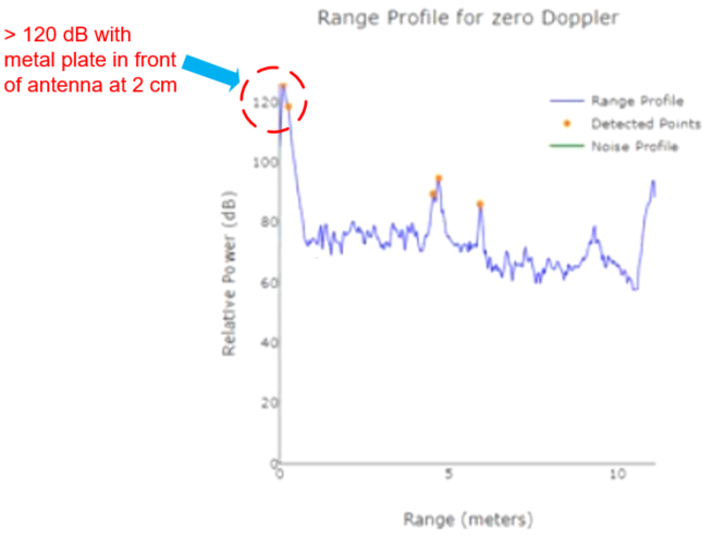
I have a few practical questions on bringing strong reflectors such as metal plates close to the radar's antenna array WITHOUT making physical contact as part of a set of experiments I am running.

1 - If I cover the front of the radar antenna while it is transmitting at full power using a 4 cm x 4 cm copper plate positioned 2 cm away from the antenna array, is this likely to damage the sensor in any way?

2 - Is there a maximum amount of time the metal plate mentioned in question 1 can be kept in front of the radar antenna at 2 cm distance without damaging the radar?

3 - If the above metal plate antenna cover tests are repeated over time, are these likely to cause radar performance degradations in the medium to long run or the radar module has the required protection against such exposure and can work reliably regardless of these repeated tests?

4 - Is there any word of caution I should be aware of based on the metal exposure to the radar antenna at such close proximity (i.e. 2 cm) ?

Thank you in advance for your help.

Regards,
Cagri

  • 1 - If I cover the front of the radar antenna while it is transmitting at full power using a 4 cm x 4 cm copper plate positioned 2 cm away from the antenna array, is this likely to damage the sensor in any way?

     [TI] It’s not going to be damaging, Absolute max power that receiver could tolerate is 10dBm.

    With the Tx and Rx isolation and path loss would be large enough so as not to violate this spec.

    https://e2e.ti.com/support/sensors/f/1023/p/843555/3119144#3119144


     2 - Is there a maximum amount of time the metal plate mentioned in question 1 can be kept in front of the radar antenna at 2 cm distance without damaging the radar?

    [TI] As long as 10dBm spec is not violated there is no problem in terms of time.


    3 - If the above metal plate antenna cover tests are repeated over time, are these likely to cause radar performance degradations in the medium to long run or the radar module has the required protection against such exposure and can work reliably regardless of these repeated tests?

    [TI]  There is 1-dB compression point at -8dBm power level, This may introduce non-linearity in the Rx measurement system, that may results in erroneous results.

     4 - Is there any word of caution I should be aware of based on the metal exposure to the radar antenna at such close proximity (i.e. 2 cm) ?

    [TI] Metal exposure to such close proximity results may not be accurate. From reliability perspective as long as power levels on the receiver port is less than 10dBm there is no harm. 

    Regards,

    Jitendra

  • Hi Jitendra,

    Thank you for this clarification. It does shed some light to my question. To make sure I understand it correctly, I am following up with a sample data capture below.

    The plot below shows the relative power on a range profile plot I captured using mmWave Demo Visualizer when a copper plate of 3 cm x 3 cm was placed directly in front of the radar's antenna array at 2 cm separation. As you can see, the relative power at around 0 meters range (which is the metal plate in front of the antenna basically) exceeds 120 dB mark. I am not sure how this is related to the 10 dBm receiver limitation you mentioned in your previous message. Can you please elaborate on the relationship between this relative power and the received power you talked about?

    Another related question I have is there a tool that will tell me the received power on the radar directly in real-time (similar to mmWave Demo visualizer)? If there is a simple way to calculate the actual received power in dB using the visualizer's relative power that would also help. I just want to make sure that I stick to sub 10 dBm receive power limit you mentioned in order not to damage AWR1642 BOOST board.

    Thank you for your help.

    Regards,

    Cagri

  • Hello Cagri,

    You cannot convert the 120dB number directly to the dBm value on Rx input since this is within the HPF region. But I don't think you need to worry about damaging the device as such since the Tx o/p itself is 11-12 dBm . So the reflection from the metal plat cannot cross the 10dBm value on the Rx input.

    While we don't see any risk of damaging the device you would be aware that keeping a metal plate in front of the antenna would prevent detection of any object beyond the metal plate. So what is the intended use case and what are you trying to measure?

    Regards,

    vivek

  • Hi Vivek,

    Thank you for confirming that the 2 cm proximity of a metal in front of the antenna will not damage the radar transceiver.

    Is there a tool that can report on the received power in terms of dBm? What is the best way of calculating the received power using the captured *.dat files from the mmWave Demo visualizer (if any)? If there is documentation you suggest I look up for this, that would be really helpful for me.

    I am aware that such an arrangement will prevent object detection by the radar and I am using this phenomenon as a feature in a set of experiments I am designing at the moment.

    Regards,

    Cagri

  • Hello Cagri,

    We do not have any tool that would directly provide the dbm value at the LNA input. you an refer to the following e2e thread to calculate it using the ADC code peak amplitude : e2e.ti.com/.../916374.

    Additionally you need to account for the HPF filtering since your object is very close and it will fall within the HPF region. We have two HPFs, each a single pole. Hence each of them will provide 20dB attenuation per decade from the cut off frequency you are programming. Add this attenuation values to the ADC dBFS value before converting it to dBm.

    Regards,

    Vivek

  • Hi Vivek,

    Thanks for the info.

    Could you please check that the link you sent is working? When I try to access it, I get a runtime error. Do you have an alternative link for me?

    Regards,

    Cagri

  • Hello Cagri,

    Can you try this link: https://e2e.ti.com/support/sensors/f/1023/t/916374

    regards,

    Vivek

  • Thanks Vivek. The last link you shared worked and has the information I was looking for.

    Regards,

    Cagri