This thread has been locked.

If you have a related question, please click the "Ask a related question" button in the top right corner. The newly created question will be automatically linked to this question.

AWR2243BOOST: SPI control of the chip without mmwave studio

Part Number: AWR2243BOOST
Other Parts Discussed in Thread: AWR2243, DCA1000EVM

Hello,

             I wanted to know whether there is any method to connect the AWR 2243 to connect to laptop over SPI without using mmWave studio GUI (preferably over Linux , but if  for Linux its not available then over Windows is also fine for us).   

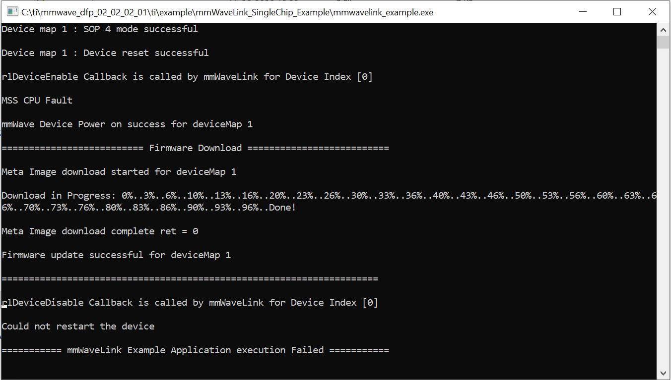
I tried the "mmwavelink_example.exe" provided in the dfp. but it doesnt seem to work.

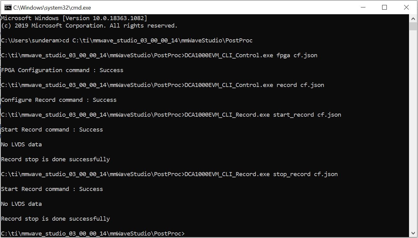
Background: I want to send configuration and commands to the AWR 2243 board over matlab (without using the mmWave studio GUI) and then recieve data over LVDS through DCA 1000. 

Kindly let me know how I should proceed for the same.

Regards,

Mohan Sunderam

  • Hello Mohan,

    Yes, you can use the mmWavelink_example and DCA1000 CLI Tool for this purpose.

    Can you let us know the error you're getting while running the exe?

    Also, we've addressed a similar query recently, so just wanted to share those insights with you....might be useful for you (please see below).

    As it's a long thread, I suggest you to only read the problem statement and the last 3-4 interaction messages (that summarizes the plan of action).

    Let us know if you need further clarification.

    Regards,

    Ishita 

  • Hello Ishita,

    This is the error I receive.  MSS CPU Fault and Could not reset the device

    Regards,

    Mohan Sunderam

  • Also another question regarding the same topic is where do I find this: DCA1000 CLI Tool. Is it part of mmwave studio or I have to downlaod separately.

    regards,

    Mohan 

  • Hello Mohan,

    Please refer to some suggestions below:

    1. For the DCA1000 CLI tool details, please refer to section 7 of the mmWave_DFP_user_guide.pdf that comes as a part of the DFP Package (docs folder). The tool is a part of mmWave Sudio.

    2. I see you're using DFP 02_02_02_01. This package is specifically for AWR2243 ES1.1 devices. In case you have AWR2243 ES1.0, please use the DFP package compatible with your device. You can check the package release notes for that. 

    3. MSS CPU fault error is a known issue in AWR2243 1.0 devices during boot up. It won't affect any device functionality, and you can proceed further with your testing. 

    4. Now regarding the error you're getting, I recommend you to first ensure if you're using the correct firmware, then let me know if you're getting any error with that.

    Regards,

    Ishita

  • Hello Ishita,

                    Thank you for the info on the dfp. I changed the DFP im using from mmwave_dfp_02_02_02_01 to mmwave_dfp_02_01_05_03 and I am able to connect to the AWR 2243 boost board but I still dont see any data in adc_data(the data doest gets over writtern from previous measurement done from mmWave studio ). I get the DCA1000EVM_CLI_Control.exe and DCA1000EVM_CLI_Record.exe application to sucess command on the command line. But dont see the data in the .bin file.

    Also just out of curiousity what is this MSS CPU fault and why does it pop up.

    Looking forward to your response.

    Regards,

    Mohan Sunderam

  • Hello Mohan,

    So you're not getting any error as such with DFP 02_01_05_03? Just not getting the data in the bin file, is that correct? Let me also try this at my end with the same DFP and I'll get back to you latest by tomorrow.

    Regarding the MSS CPU Fault error, it comes during bootup due to a register read-back failure in AWR2243 ES1.0 devices, but as I said, it wont affect any functionality.

    Regards,

    Ishita 

  • Hello Mohan,

    Instead of using mmWave link example, can you try this first mmWave studio first? Let's make sure the CLI tool is able to capture using studio atleast.

    Regards,

    Ishita

  • Hello Ishita,

                  So I tried the following as suggested by you.

    1. Connected the AWR 2243 through mmWave studio 3.0.0.14

    2. Set all the required parameters

    3. Connected to DCA 1000 EVM board through mmWave studio

    4. Through cmd line commands tried to get the data from DCA 1000 

    I still dont get any data: No LVDS data captured is the message (see image). So is it safe to assume that the CLI is the issue ?

    Regards,

    Mohan

  • Hello Mohan,

    Thankyou for doing the experiment. 

    Can you also let me know if the capture fails when not using the CLI tool? i.e. using mmWave studio only for configuration and capture. 

    Please check if you get the same message of NO LVDS DATA when using studio.

    This way, we can know if it is configuration problem with DCA1000 or CLI issue. 

    Also make sure to flash the correct and latest version of FPGA firmware in DCA1000

    Regards,

    Ishita

  • Ishita,

     I already did that.

    With mmwave studio everything works well. But with the CLI tool I dont get anydata.

    I already flashed the latest FPGA firmaware using the Lattice Diamond flashing tool.

    Looking forward to your guidance about the same.

    Regards,

    Mohan Sunderam

  • Hello Mohan,

    The JSON file which the CLI uses as input is same for the mmWaveStudio use case and the DCA1000 stand-alone use case.

    Please check for the following:

    1. Once the start_record command is given, wait for one-two seconds for a temporary CLI to open up in the background which indicates that the process is ready to capture. At this point of time, trigger the frames. Once the frames has ended, within a second or two, the temporary CLI closes back again. This indicates that the capture was successful. Else, even before the start record process has started and if the frames are triggered, the DCA1000 won’t be capturing anything and it results in the NO_LVDS_DATA_RECEIVED command.
    2. Check your json file as well and make sure all parameters are correct.

    You can view the csv file which displays the stats of the capture and the corresponding bin file. There is also a file called CLI_LogFile.txt which gets created for every command that is sent through the CLI. (for debugging purposes)

    Please try and let us know.

    Regards,

    Ishita

  • Hello Ishita,

                    This method capture works but this doesnt still solve my issue of collecting data from AWR 2243 board without using the mmWave GUI. I still have to set parameters and trigger the frame through the mmWave studio in this method. So to try something out I have the following questions so as to by pass mmWavestudio gui

    1. To connect to the AWR 2243 boost through mmwavelink_example.exe do I need to change the SOP jumpers configuration ?

    2. I assume I can directly connect to the AWR 2243 through the mmwavelink_example.exe without using the mmWave studio even for SPI connect. Am I right to assume that ?

    3. What is the maximum FOV for the AWR 2243 (min and max angles)- Azimuth ? 

    With best regards,

    Mohan Sunderam

  • Hello Mohan,

    Yes I understand your concern.

    mmWave link and DCA1000 CLI utility together can provide a method to capture raw ADC data through LVDS without mmWave studio. The reason I am asking you to use studio first is just to make sure the DCA1000 CLI utility works good for you in the first place. After we have that confirmation, you can move to mmWave link.

    Also, coming to your questions, you can read about mmWave link examples in the mmWave_DFP_user_guide.pdf. You would need usual SOP 4 mode and yes it provides the SPI connection.

    Regards,

    Ishita

  • Hello Ishita,

     Thank you for your response. I shall go through the examples in the DFP. Can you also answer the question of the Field of View (FOV) : whether it is tunable and the limits of tunning.

    Regards,

    Mohan

  • Hello Mohan,

    Please refer to the below links :

    Programming Chirp Parameters in TI Radar Devices

    Regards,

    Ishita

  • Hello, 

              the mmwavelink is working but if I change the settings in the mmwaveconfig.txt then the mmwavelink_example.exe stops functioning and there is an error BSS CPU fault or MSS RF error.

    The dynamic profile and chirp settings are enabled by default and I wanted to disable it so that I can use the same setting that I use in mmWave studio. Also I switched off the Advanced frame settings and I get the same error as stated before.

    With best regards,

    Mohan Sunderam

  • Hello Mohan,

    Let me try this experiment on my part and I will get back to you next week with my observations.

    Regards,

    Ishita

  • Hello Ishita,

               Looking forward to more observations from your side soon.

    Thank you,

    WIth best regards,

    Mohan Sunderam

  • Hello Mohan,

    I was successfully able to run the example even with Dynamic and Advance settings disabled. 

    Can you send me the trace file generated in your experiment? Do send the configuration file as well. 

    Regards,

    Ishita

  • Hello Ishita,

                       Thank you for the response.

    I have attached the Trace and config text files.

    Regards,

    Mohan Sunderam

    #
    #For detailed view of mmWave Radar configuration structure
    #please refer 
    #ti\control\mmwavelink\docs\doxygen\html\index.html
    #
    
    #
    #Global configuration
    #Advanced frame test enable/disable; 1 - Advanced frame; 0 - Legacy frame
    #Continuous mode test enable/disable; 1 - Enable; 0 - Disable
    #Dynamic chirp test enable/disable; 1 - Enable; 0 - Disable; This should not be enabled if Advanced chirp test is enabled
    #Dynamic profile test enable/disable; 1 - Enable; 0 - Disable
    #Advanced chirp test enable/disable; 1 - Enable; 0 - Disable; The legacy chirp API is not required if this is enabled
    #Firmware download enable/disable; 1 - Enable; 0 - Disable
    #mmWaveLink logging enable/disable; 1 - Enable; 0 - Disable
    #Calibration enable/disable; To perform calibration store/restore; 1 - Enable; 0 - Disable
    #Calibration Store/Restore; If CalibEnable = 1, then whether to store/restore; 1 - Store; 0 - Restore
    #Transport mode; 1 - I2C; 0 - SPI
    #Flash connected enable/disable; 1 - Enable; 0 - Disable
    #
    LinkAdvanceFrameTest=0;
    LinkContModeTest=0;
    LinkDynChirpTest=0;
    LinkDynProfileTest=0;
    LinkAdvChirpTest=0;
    EnableFwDownload=1;
    EnableMmwlLogging=1;
    CalibEnable=1;
    CalibStoreRestore=1;
    TransferMode=0;
    IsFlashConnected=0;
    #END
    
    #
    #power on master arguments, please modify if needed.
    #rlClientCbs_t: crcType 0:16Bit/1:32Bit/2:64Bit, ackTimeout
    #
    crcType=2;
    ackTimeout=1000;
    #END
    
    #
    #channel config parameters, please modify if needed.
    #rlChanCfg_t
    #
    channelTx=3;
    channelRx=15;
    cascading=0;
    #END
    
    #
    #ADC out config parameters, please modify if needed.
    #rlAdcOutCfg_t
    #
    adcBits=2;
    adcFormat=2;
    #END
    
    #
    #DATA format config parameters, please modify if needed.
    #rlDevDataFmtCfg_t
    #
    rxChanEn=15;
    adcBitsD=2;
    adcFmt=1;
    iqSwapSel=0;
    chInterleave=0;
    #END
    
    #
    #Low power config Paramters, please modify if needed.
    #rlLowPowerModeCfg_t
    #
    anaCfg=0;
    lpAdcMode=3;
    #END
    
    #
    #Data Path config parameters, please modify if needed
    #rlDevDataPathCfg_t
    #
    intfSel=1;
    transferFmtPkt0=1;
    transferFmtPkt1=0;
    cqConfig=2;
    cq0TransSize=64;
    cq1TransSize=64;
    cq2TransSize=64;
    #END
    
    #
    #LVDS clock config parameters, please modify if needed
    #rlDevDataPathClkCfg_t
    #
    laneClk=1;
    dataRate=1;
    #END
    
    #
    #SET HSI clock parameters, please modify if needed.
    #rlDevHsiClk_t
    #
    hsiClk=9
    #END
    
    #
    #LANE config parameters, please modify if needed.
    #rlDevLaneEnable_t
    #
    laneEn=15;
    #END
    
    #
    #LVDS Lane Config parameters, please modify if needed.
    #rlDevLvdsLaneCfg_t
    #
    laneFmtMap=0;
    laneParamCfg=1;
    #END
    
    #
    #Programmable Filter config parameters, please modify if needed.
    #rlRfProgFiltConf_t
    #
    profileId=0;
    coeffStartIdx=0;
    progFiltLen=14;
    progFiltFreqShift=100;
    #END
    
    #
    #Profile config parameters, please modify if needed.
    #rlProfileCfg_t
    #
    profileId=0;
    pfVcoSelect=2;
    #startFreqConst=1439117143;
    startFreqConst=1435388860;
    idleTimeConst=1000;
    adcStartTimeConst=600;
    rampEndTime=6000;
    txOutPowerBackoffCode=0;
    txPhaseShifter=0;
    freqSlopeConst=621;
    txStartTime=0;
    numAdcSamples=256;
    digOutSampleRate=10000;
    hpfCornerFreq1=0;
    hpfCornerFreq2=0;
    rxGain=30;
    #END


    #
    #Chirp Configuration parameters, please modify if needed.
    #rlChirpCfg_t
    #
    chirpStartIdx=0;
    chirpEndIdx=0;
    profileIdCPCFG=0;
    startFreqVar=0;
    freqSlopeVar=0;
    idleTimeVar=0;
    adcStartTimeVar=0;
    txEnable=3;
    #END
    
    #
    #Chirp Configuration parameters, please modify if needed.
    #rlChirpCfg_t
    #
    #chirpStartIdx=1;
    #chirpEndIdx=1;
    #profileIdCPCFG=0;
    #startFreqVar=0;
    #freqSlopeVar=0;
    #idleTimeVar=0;
    #adcStartTimeVar=0;
    #txEnable=2;
    #END
    
    #
    #Chirp Configuration parameters, please modify if needed.
    #rlChirpCfg_t
    #
    #chirpStartIdx=2;
    #chirpEndIdx=2;
    #profileIdCPCFG=0;
    #startFreqVar=0;
    #freqSlopeVar=0;
    #idleTimeVar=0;
    #adcStartTimeVar=0;
    #txEnable=3;
    #END
    
    #
    #Frame configuration parameters, please modify if needed.
    #rlFrameCfg_t
    #
    chirpStartIdxFCF=0;
    chirpEndIdxFCF=0;
    frameCount=0;
    loopCount=1;
    periodicity=10000000;
    triggerDelay=0;
    numAdcSamples=256;
    triggerSelect=1;
    #END


    #
    #Continuous mode config parameters
    #startFreqConst=1435384036;
    #txOutPowerBackoffCode=0;
    #txPhaseShifter=0;
    #digOutSampleRate=10000;
    #hpfCornerFreq1=0;
    #hpfCornerFreq2=0;
    #contModeRxGain=30;
    #vcoSelect=3388;
    #end
    
    
    #
    #Advanced chirp Profile config LUT parameters
    #Each data parameter is 4 bits
    #AdvChirpLUT_ProfileConfig_LUTAddrOff=0;
    #AdvChirpLUT_ProfileConfig_Data1=0;
    #AdvChirpLUT_ProfileConfig_Data2=1;
    #AdvChirpLUT_ProfileConfig_Data3=2;
    #AdvChirpLUT_ProfileConfig_Data4=3;
    #end
    
    #
    #Advanced chirp Start Freq config LUT parameters
    #The Start Freq data is in GHz
    #Each data parameter is 1 or 2 or 4 bytes depending on ParamSize
    # ParamSize    Size in bytes
    #     0             4
    #     1             2
    #     2             1
    #AdvChirpLUT_StartFreqConfig_LUTAddrOff=4;
    #AdvChirpLUT_StartFreqConfig_ParamSize=1;
    #AdvChirpLUT_StartFreqConfig_ParamScale=0;
    #AdvChirpLUT_StartFreqConfig_Data1=-0.000001;
    #AdvChirpLUT_StartFreqConfig_Data2=0.000000;
    #AdvChirpLUT_StartFreqConfig_Data3=0.000001;
    #AdvChirpLUT_StartFreqConfig_Data4=-0.000001;
    #end
    
    #
    #Advanced chirp Freq Slope config LUT parameters
    #The Freq Slope data is in MHz/us
    #Each data parameter is 1 byte
    #AdvChirpLUT_FreqSlopeConfig_LUTAddrOff=12;
    #AdvChirpLUT_FreqSlopeConfig_Data1=-0.050;
    #AdvChirpLUT_FreqSlopeConfig_Data2=0.000;
    #AdvChirpLUT_FreqSlopeConfig_Data3=-0.050;
    #AdvChirpLUT_FreqSlopeConfig_Data4=0.050;
    #end
    
    #
    #Advanced chirp Idle time config LUT parameters
    #The Idle time data is in us
    #Each data parameter is 1 or 2 bytes depending on ParamSize
    # ParamSize    Size in bytes
    #     0             2
    #     1             1
    #end


  • Also can you attach the trace file you got when the example was succesful for reference.

    Thank you in advance

  • Hello Mohan,

    Here is the trace file I got with my experiment : 2134.trace.txt

    Let me study your config and trace file, and I will get back to you in a day or two.

    Regards,

    Ishita

  • Hello Ishita,

     As far as I have checked the traces files, both of them look pretty similar.

    Maybe you can share more details soon.

    With best regards,

    Mohan

  • Hello Mohan,

    For now you can change the crc value as "1" i.e. 32 bit in the mmwaveconfig.txt file and proceed ahead with your experiment.

    Regards,

    Ishita

  • Hello Ishita, 

                    I tried with changing the CRC value to 1 and it still doesnt work. I hope you have had time to perform more measurements and hence have more inputs for me.

    Regards,

    Mohan Sunderam

  • Hello Mohan,

    In addition to the CRC value, please keep lpAdcMode=0.

    Sorry, I forgot to mention this earlier.

    Regards,

    Ishita

  • Hello Ishita,

    I will try and let you know whether this works for me.

    best regards,

    Mohan

  • Hello Ishita,

     I tried changing the said parameters and also with the right SOP mode(4). I get the same mmWave device error -8.

    Can you please check this issue for me.

    Regards,

    Mohan

  • Hello Mohan,

    I remember previously you were getting a BSS CPU fault error before RF INIT. I was getting the same error when I tried with your mmWaveconfig.txt file, but it was resolved with the above mentioned two changes. 

    Now when are you getting this error code -8? It seems this time its a connection issue.

    Regards,

    Ishita