This thread has been locked.

If you have a related question, please click the "Ask a related question" button in the top right corner. The newly created question will be automatically linked to this question.

FDC2112: FDC2112. I2C bus no ACK

Part Number: FDC2112


Hi,

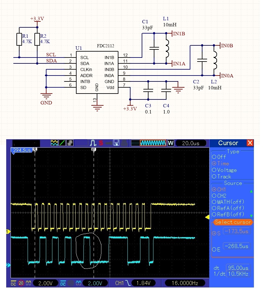
I made a schematic according to the datasheet.
But I2C bus FDC2112 doesn't work.
FDC2112 is not responding. No ACK from this chip.


Thank you in advance.
Aleksandr

  • Alexandr,

    Thank you for your post and your interest in TI products.

    Your schematic shows the ADDR pin tied to ground, which sets the I2C address to 0x2A.
    If it's HIGH, the I2C address is 0x2B. Could that be the problem?

    Regards,
    John

  • Thank you for your reply.

    Now I can't verify the other I2C address 0x2B .
    This requires another PCB.

    Please check the typos in the documentation  "FDC 2212...      SNOSCZ5A - JUNE 2015- REVISED JUNE 2015".:

    1. Table 47. Recommended Initial Register Configuration Values (Multi-channel Operation)
         Value -  0x8329  ????hexadecimal??????
       page 42   5b):   8329 (decimal)
       page 43   5c):   0x2089    - this is 8329 (decimal)


    2. Table 41. Address 0x1E, DRIVE_CURRENT_CH0 Field Descriptions
         15:11 CH0_IDRIVE  R/W 0000 0   - 5 (!)   bits MSB

       Page 42 "...DRIVE_CURRENT_CH0 register (addr 0x1E) is 0x7C00."   This is  6 (!)   bits MSB


       Table 47. Recommended Initial Register Configuration Values (Multi-channel Operation)
         VALUE 0x7C0. This is  6 (!)   bits MSB


    Regards,

    Alexandr

  • Alexandr,

    Thank you for your feedback. 
    We will review the details you have provided and rev the data sheet to correct any confusing or inconsistent items.

    Thanks again.
    John

  • John,

    I found a solution to my problem I2C.
    First you need to transfer dummy transaction to any free I2C address (need 9 SCL pulses).

    However, the sensor is not working properly yet.
    I am using FDC2112 and therefore changed the settings from datasheet page42.
    Single-ended Sensor Configuration. And Single-Channel Opetation.
    Channel0 .


    Initial Register Configuration Value:
    1). CLOCK_DIVIDER_CH0 (0x14)   -  value = 0x2001
    2). DRIVE_CURRENT_CH0 (0x1E)   -  value = 0x7C00   (or 0x7800)
    3). SETTLECOUNT_CH0   (0x10)   -  value = 0x000A
    4). swiching delay not need for Single-Channel Opetation
    5). RCOUNT_CH0          (0x08)   -  value = 0x2089
    6). ERRO_CONFIG default
    7). MUX_CONFIG register not used
    8). CONFIG          (0x1A)   -  value = 0x0081


    Meassure:
    STATUS     (0x18)  -   value = 0x0008
    DATA_CH0   (0x00)  -   value = 0x0FFF (over range)

    On L-C tank (18uH; 33pF):  IN0A & IN0B  - no signal.
    I see by oscilloscope.


    What am I configuring wrong?

    Regards,

    Alexandr


  • Alexandr,

    Thank you for the additional info.
    This will take a little time to review, and I may have to tap some of my colleagues' expertise.

    I will provide an update by Monday

    Regards,
    John

  • Alexandr,

    We are still looking at your findings, and should have some suggestions - or questions - in a day or two.

    Regards,
    John

  • Hello Alexandr, 

    I was unable to recreate your issue. Having no signal on the input traces while also having a data ready signal in the status register is a weird combination. Can you clarify how you have the sensor connected and how you are probing the signals? 

    Thank you, 

  • Hello  Justin,

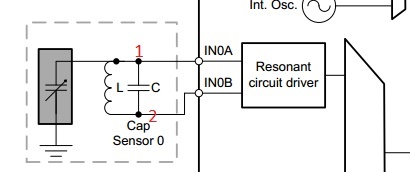
    I am monitoring the signal with an oscilloscope at points 1 and 2 (red color). On an L-C tank.


    Sorry, c I encountered a PCB mounting error. :-(
    Instead of an inductor of 18uH, 18nH was used.


    I am now expecting an 18uH inductance to arrive.
    It will take several days.


    Please tell me.
    Have I configured the FDC2112 correctly?


    Redards,
    Alexandr

  • Hello Alexandr, 

    Points 1 and 2 will be the same signal so you will only need to monitor one of them to see the sensor oscillation. 

    As for your configuration, you will want to double check the current drive once you have the new inductor placed but I don't see anything that should be a problem. With your current inductor, you could try adjusting the clock divider to see if you can get an oscillation once that is set for that frequency if you want to do some testing in the meantime. Otherwise, let me know what the status is once you have the new inductor.

    Best Regards, 


  • Hello Justin,

    I changed the inductor to 18uH.
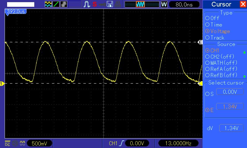
    Now the oscillation amplitude is 1,4V.  ~5MHz.

    DATA_CH0 without touch:  2698
    DATA_CH0 with touch:       2409

    Output_gain=0x03


    However I need proximity detection >=5mm.
    How to increase sensitivity?


    Redards,
    Alexandr

  • Hello Alexandr, 

    I would start by increasing the sensor drive current which will also increase the oscillation voltage. Increasing this until the oscillation is closer to a 1.8V peak without going over should yield better results at farther distances. 

    Best Regards,