This thread has been locked.

If you have a related question, please click the "Ask a related question" button in the top right corner. The newly created question will be automatically linked to this question.

TMP175: About TMP175 .. How many devices can I connect to the I2C BUS

Part Number: TMP175
Other Parts Discussed in Thread: TCA9517, TMP1075

hello

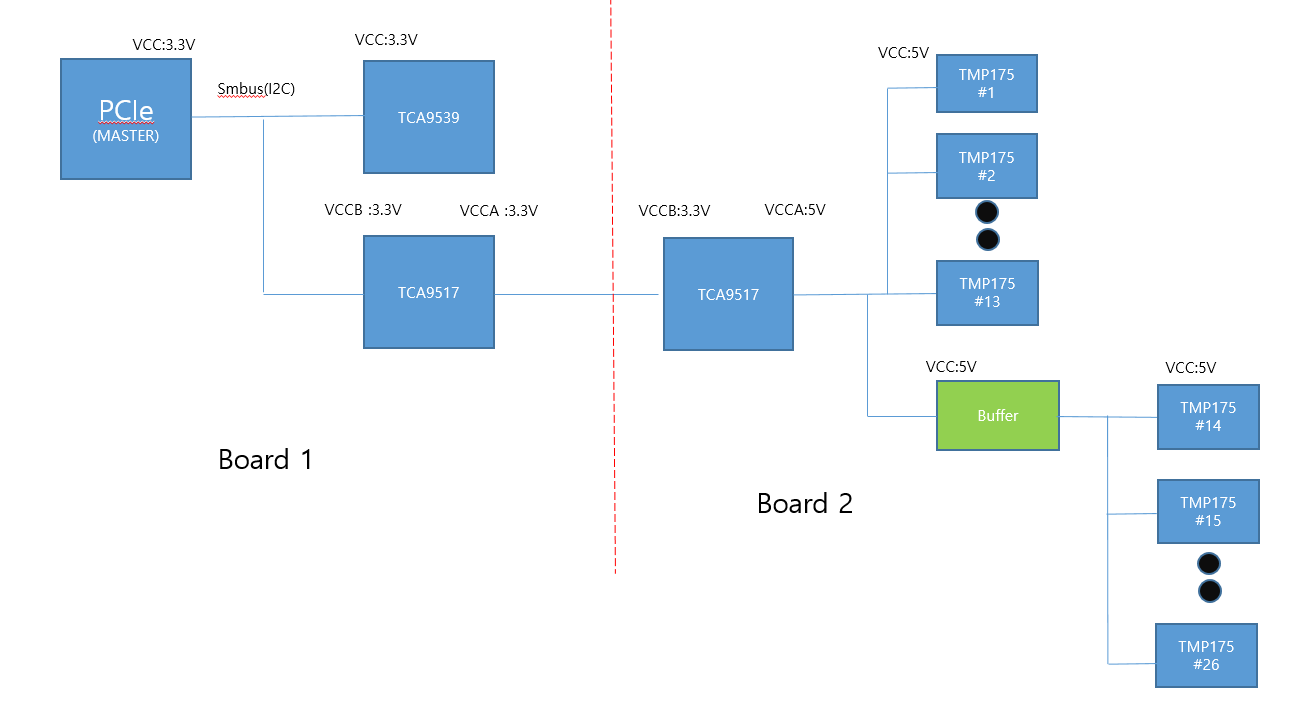
I try to measure temperature using TI device (TMP175).

There is only one bus which is communicating with I2C, but I need 26EA device(TMP175) in parallel.

I had two concern, First I need device which have many slave address . Second I need to reduce bus capacitance. (limit 400pf in I2C )

That's why I chose TMP175 and I decide to add buffer. But I don't know what i have to choose yet. 

I attached my block diagram. Is there any problem ?  Could you plz recommend any solution and you can choose buffer ( TI's device)

Board 1 is made already . I try to design board 2 now.  3.3V power is short in board 2 . So I have to use TCA9517 to shift to 5V.

Thank you.

  • Hi,

    The TMP175 does have up to 27 different addresses so this should meet your 26 different address requirement. 

    Do you have concerns with the I2C bus after the 2nd TCA9517 capacitance being too high?  Each TMP175 input capacitance should be ~3pF which would be under the 400pF max.  if you are concerned with the capacitance still though is there a reason you wouldn't want to use another TCA9517 as a buffer?

    The TMP1075 has up to 32 addresses and has better accuracy and current consumption which may help in your application seeing that you are using many of these devices.  

    Thanks,

    David

  • Hi, David

    Thank you for your recommend.

    Let me reply below questions.

    The TMP175 does have up to 27 different addresses so this should meet your 26 different address requirement. 

    --> I think so .

    Do you have concerns with the I2C bus after the 2nd TCA9517 capacitance being too high?  Each TMP175 input capacitance should be ~3pF which would be under the 400pF max.  if you are concerned with the capacitance still though is there a reason you wouldn't want to use another TCA9517 as a buffer?

    -->  Yes I am worry about that as you mention.  

           I attached circuit board 2  but a little bit different compare to previous blockdiagram.  Could you please check that out?

          TCA9517#1 : For voltage level shift because of different vcc voltage between slave and  master.

          TCA9546 ( IC Switch ) : Separation CH . For reducing bus capacitance and long bus which makes spike noise in data line. 

          TCA9517#2,3,4,5(As buffer)  : For reducing bus capacitance 

          I will change resistor value after calculation.

          If you have another solution  Please let me know.

    The TMP1075 has up to 32 addresses and has better accuracy and current consumption which may help in your application seeing that you are using many of these devices.  

    --> I think , address number is enough now.  But let me consider this part.

    circuit.pdfcircuit.pdf

    Thanks,

  • Hi,

    I have a couple concerns with your schematic. 

    1. There is no net on the TCA9546 I2C Switch to control what channels to enable and communicate to the different devices. 

    2. There are many redundant pull-up resistors on the I2C bus which will create a very strong pull up since they all will be in parallel.  

    Thanks,

    David

  • Hi David

    Thank you for your review.

    I renewal my circuit what you recommendation.

    Let me attached my circuit new version. Please check that out one more. 5811.circuit.pdf

    1. There is no net on the TCA9546 I2C Switch to control what channels to enable and communicate to the different devices. 

    I missed , I connect this net.

    2. There are many redundant pull-up resistors on the I2C bus which will create a very strong pull up since they all will be in parallel.  

    I removed redundant pull-up resistors.

    Thank you

  • Hi,

    It looks like you still have redundant pull-up resistors on SMB_SCL_0 and SMB_SDA_0 (10KΩ and 470 Ω).  This would make a very strong pull-up resistor.  If this was you intention then it could be ok if this sized pull-up allows for proper timing and Vol and Iol of the devices.  For reference you can see this app note to determine pull-up resistor size range.  

    https://www.ti.com/lit/an/slva689/slva689.pdf?ts=1603373322708&ref_url=https%253A%252F%252Fwww.google.com%252F

    It also looks like for some of the addressing you plan on using a resistor divider or pulling up/down via a 4.7 kΩ resistor.  These pins should be strictly floated, or tied to VCC/GND directly.  

    Thanks,

    David