This thread has been locked.

If you have a related question, please click the "Ask a related question" button in the top right corner. The newly created question will be automatically linked to this question.

TDC7200: Hardware configuration questions for SPI R/W using Arduino

Part Number: TDC7200
Other Parts Discussed in Thread: , TDC1000

Hello,

As previously discussed, I've managed to read the default values for the TDC7200EVM, and write to it using the Arduino. However, my problem now is that I am unable to write to just the IC. Here was the last question on the related thread:

Thank you for the help so far. I've managed to R/W to the TDC7200 on the EVM using the Arduino programme, by soldering some connections from the Arduino to the test points. However, I haven't found the same success in performing R/W to just the IC, so it's likely an issue with me making incorrect hardware connections.

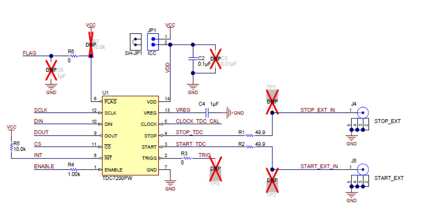
That being said, may I check If all the resistors and capacitors (C2/C4, R1-R6) present on the TDC7200EVM are necessary for the TDC7200 to function? The capacitors/resistors in question are from the TDC7200EVM, shown below:

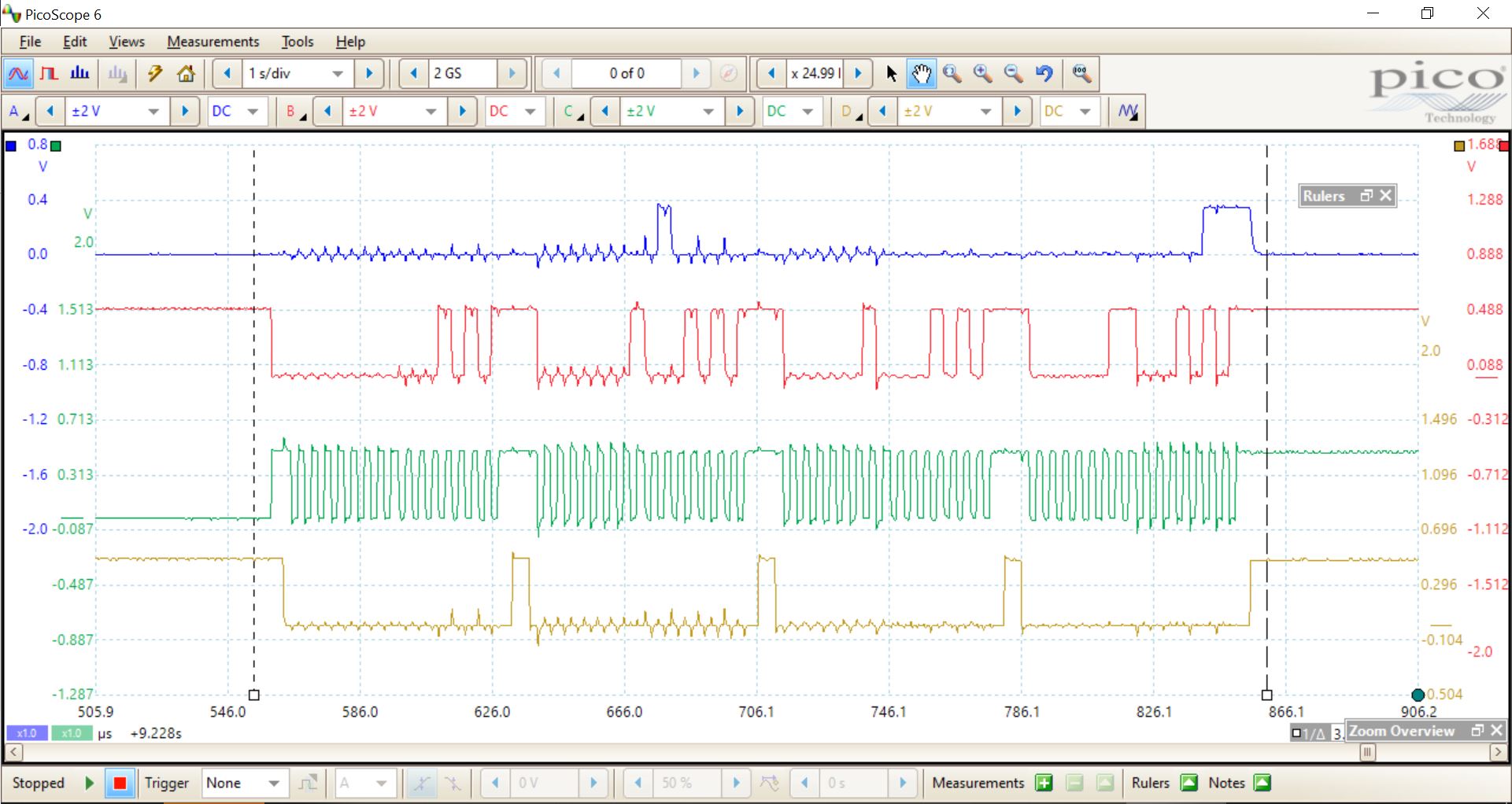
Additionally, I tried reading the default values for the first 4 registers on the TDC7200 for both the EVM (top) and the IC (bottom).Below are the SPI R/W signals obtained the EVM and the IC.I am now using CPOL = 0 and CPHA = 0.

Blue - DIN          Red - DOUT        Green - SCLK        Yellow - CS

EVM scope readings:

IC scope readings:

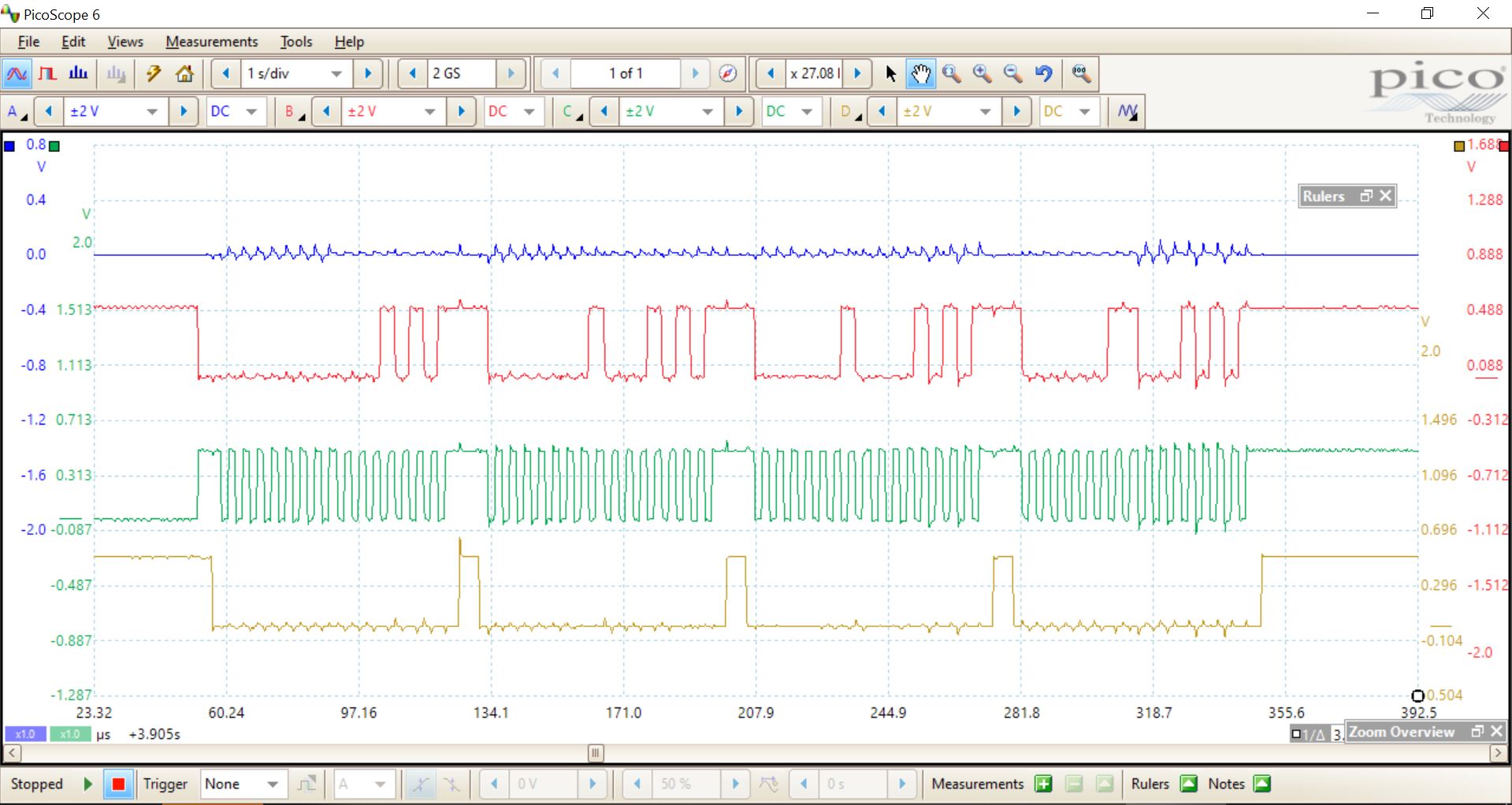
I'm not sure why but it seems that for the case of just the IC there is no DOUT signal at all, even though the Arduino is sending the same signal to DIN.

Thank you.

Regards,

Jack

  • Hi Jack,

    C2: This is the supply decoupling capacitor. These are always recommended because they act as a filter for noise on the power rail and also a quick source of current when the device current draw spikes. Using a decoupling capacitor can prevent glitches in device operation. See these technical articles for more info and layout guidelines: the-decoupling-capacitor-is-it-really-necessary and bypass-capacitors-yes-but-why

    C4: This is also a decoupling capacitor, but for the TDC7200 internal LDO. 

    Bypass capacitor failure is sometimes a cause of device failure, see post 3299497

    R1, R2: These are impedance matching resistors to match the 50 Ohm impedance of the coax cable that would connect to the START and STOP pins via the SMA connectors on the EVM. The need for these resistors depends how you connect these pins to the TDC1000. If connected to the TDC1000 on the same PCB, the resistors should not be needed, just use short, length matched signal traces. Also note, if glitches (false positives) are seen on the START/STOP pins, installing these resistors (or larger values) combined with the START/STOP input capacitance can provide low pass filtering that rejects glitches. It may be a good idea to include space for them in PCB prototypes. 

    R3: This 0 Ohm resistor gives access to the TRIGG pin on the EVM, design dependent.

    R4: This resistor is recommended for filtering on the ENABLE pin, since a glitch in this pin would reset the device. 

    R5: INTB is active low, so a pull-up resistor is needed here.

    R6: Not required.

    Following the Layout guidelines and using all recommended passive components is the best starting place when prototyping a new design. 

    I hope this helps!

    Regards,

    Gabriel