This thread has been locked.

If you have a related question, please click the "Ask a related question" button in the top right corner. The newly created question will be automatically linked to this question.

IWR6843: IWR6843ISK

Part Number: IWR6843
Other Parts Discussed in Thread: MMWAVEICBOOST, ,

Hi,

This thread is a bit of a thought experiment. Im looking into getting a few EVM boards for a bistatic mm-wave radar setup/experiment.
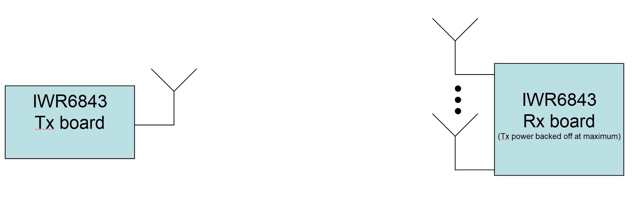
I was interested if I could set up a bistatic mm-wave radar setup using 2 IWR6843ISK boards (with the MMWAVEICBOOST cards as well). I've attached a simply block diagram of the system. I understand that both boards have tx/rx capability but the idea here is that the received signal would be ignored on the Tx Board and that the transmit signal would be at maximum backoff on the Rx Board and the echoes received and processed on the Rx Board side. Both radar boards would be setup with identical frequency operating ranges, chirps etc except the Rx board is intended to receive echoes from the tx signal generated from the Tx Board.. Keep in mind i do not plan to connect these boards in any cabled fashion so its not like the cascaded scenario. Im hoping to keep them separated as far as possible, not sure if i will be able to achieve more than 50m, but thats the goal atm. Would this setup work and what are the potential problems? Appreciate the help.  

  • Hello Dr_SP,

          For the Radar operation to work you would need same local oscillator on both the side, from which you generate a beat frequency after the down conversion. In this scenario same LO used on the Tx board would be needed on the Rx side of the board. If you had a provision to route the LO signal from Tx board to Rx board then it could have been possible...However, IWR6843 does not support this kind of configuration. Hence it may not be possible in this setup. 

    Thanks and regards,

    CHETHAN KUMAR Y.B.

  • Hi, Chethan.

    Thank you for the prompt reply. I think i understand what the problem is. In essence, due to there not being a shared LO between the Tx and Rx boards the chirps generated on each board by the transmitter would be out of sync and would result in a beat frequency that is outside of the required range the radar can process i assume. Would you say thats correct?

    Out of interest, what is the maximum beat frequency for the IWR6843? Would it be half of the ADC sampling rate (~12.5 MHz)?

  • Hi Dr_SP,

        Absolutely your statement above is correct, as there is no LO synchronization between Transmitter board and Receiver board. Hence this is the problem in this approach. 

    Maximum IF bandwidth is 10MHz as shown below from the datasheet.

    Thanks and regards,

    CHETHAN KUMAR Y.B.