This thread has been locked.

If you have a related question, please click the "Ask a related question" button in the top right corner. The newly created question will be automatically linked to this question.

AWR1843: LVDS Byte Reordering Issue?

Part Number: AWR1843

We are bringing up a new automotive radar system based on the AWR1843 chip, and we are trying to output data through LVDS. We are trying to root-cause an issue we are seeing where pairs of bytes are being reordered; we do not know whether or not it is a software issue, but if there is an obvious SW fix, we'd save some time investigating.

Here is an excerpt of the data we are seeing (header starts at byte 0x4a. payload starts at byte 0x152 and ends at byte 0x249):

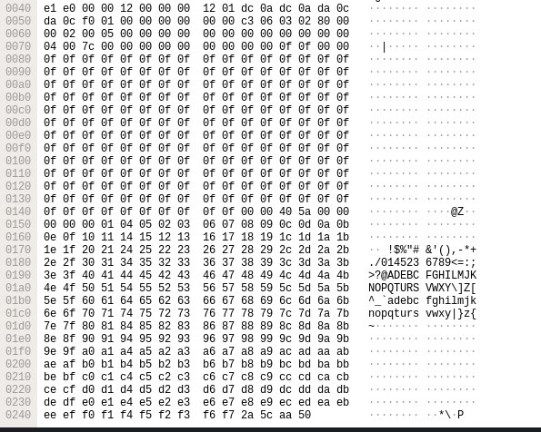
We are emitting a 1-byte counter from 0 up to 247 (0xf7) with user-defined data in a CBUFF SW session. Columns 4, 5, 6, 7, 12, 13, 14, 15 look to be ordered incorrectly. My hypothesis for the reordering is that for each row, bytes [4:5] are swapped with bytes [6:7], and bytes [12:13] are swapped with [14:15]. This would explain why the counter is out-of-order in the payload. Additionally:

- The payload is preceded by 8 bytes of an LVDS header that is composed by the TI drivers. The LVDS header is preceded by an HSI header (also composed by TI driver) which is padded to 256 bytes.
- The last segment of the HSI header is made up of padding bytes of 0x0f to bring header to 256 bytes. Bytes [0x7c:0x7d] look like they could be swapped with [0x7e, 0x7f], but this is not sufficient evidence.
- The HSI header starts at byte 0x4a with a magic number which, in this case, should be 0x0CDA0ADC0CDA0ADC.
- In the packet capture, the magic number is 0x0CDA0CDA0ADC0ADC. That is, bytes [2:3] are swapped with [4:5] which matches my hypothesis if you look at the capture (it is encoded in little-endian).This last point convinces me of the swapping; we do not manipulate the magic number ourselves.

We are continuing to investigate the issue, but it would help if there were a simple configuration option for the HSI data that we've missed.

  • Hi,

    I assume you use the mmWave SDK. What version are you using?

    thank you

    Cesar

  • We are using version 03.03.00.03 of the mmWave SDK

  • Could you help me with the config file which you are using for this experiment?

    And which demo you are using? Default code or made some change, please provide info so we can reproduce this at our end and debug further.


    Regards,

    JG

  • /*
     *  Copyright 2011 by Texas Instruments Incorporated.
     *
     *  All rights reserved. Property of Texas Instruments Incorporated.
     *  Restricted rights to use, duplicate or disclose this code are
     *  granted through contract.
     *
     */
    environment['xdc.cfg.check.fatal'] = 'false';
    
    /********************************************************************
     ************************** BIOS Modules ****************************
     ********************************************************************/
    var Memory    = xdc.useModule('xdc.runtime.Memory');
    var BIOS      = xdc.useModule('ti.sysbios.BIOS');
    var HeapMem   = xdc.useModule('ti.sysbios.heaps.HeapMem');
    var HeapBuf   = xdc.useModule('ti.sysbios.heaps.HeapBuf');
    var Task      = xdc.useModule('ti.sysbios.knl.Task');
    var Idle      = xdc.useModule('ti.sysbios.knl.Idle');
    var SEM       = xdc.useModule('ti.sysbios.knl.Semaphore');
    var Event     = xdc.useModule('ti.sysbios.knl.Event');
    var Hwi       = xdc.useModule('ti.sysbios.family.arm.v7r.vim.Hwi');
    var System    = xdc.useModule('xdc.runtime.System');
    var SysStd    = xdc.useModule('xdc.runtime.SysStd');
    var clock     = xdc.useModule('ti.sysbios.knl.Clock');
    var Pmu       = xdc.useModule('ti.sysbios.family.arm.v7a.Pmu');
    var Load      = xdc.useModule('ti.sysbios.utils.Load');
    
    System.SupportProxy = SysStd;
    
    /* FIQ Stack Usage: */
    Hwi.fiqStackSize                = 2048;
    Hwi.fiqStackSection            = ".myFiqStack"
    Program.sectMap[".myFiqStack"] = "DATA_RAM";
    
    /* Default Heap Creation: Local L2 memory */
    var heapMemParams           = new HeapMem.Params();
    heapMemParams.size          = 32*1024;
    heapMemParams.sectionName   = "systemHeap";
    Program.global.heap0        = HeapMem.create(heapMemParams);
    Memory.defaultHeapInstance  = Program.global.heap0;
    
    /* Enable BIOS Task Scheduler */
    BIOS.taskEnabled	= true;
    
    /* Reduce the size of BIOS */
    BIOS.swiEnabled        = false; /* We don't use SWIs */
    BIOS.libType           = BIOS.LibType_Custom;
    Program.stack          = 2048; /* for isr context */
    Task.idleTaskStackSize = 800;
    var Text               = xdc.useModule('xdc.runtime.Text');
    Text.isLoaded          = false;
    
    /* do not call update for load - Application will call it at inter-frame boundary */
    Load.updateInIdle = false;
    
    Program.sectMap[".vecs"]	= "VECTORS";
    
    /* Make sure libraries are built with 32-bit enum types to be compatible with DSP enum types*/
    BIOS.includeXdcRuntime  = true;
    BIOS.libType            = BIOS.LibType_Custom;
    BIOS.customCCOpts      += " --enum_type=int ";
    
    /********************************************************************
     * Enabling DebugP Log Support
     ********************************************************************/
    var Log         = xdc.useModule('xdc.runtime.Log');
    var Main        = xdc.useModule('xdc.runtime.Main');
    var Diags       = xdc.useModule('xdc.runtime.Diags');
    var LoggerBuf   = xdc.useModule('xdc.runtime.LoggerBuf');
    
    /* Configure the Logger Buffer: */
    var loggerBufParams             = new LoggerBuf.Params();
    loggerBufParams.bufType         = LoggerBuf.BufType_CIRCULAR;
    loggerBufParams.exitFlush       = false;
    loggerBufParams.instance.name   = "_logInfo";
    loggerBufParams.numEntries      = 200;
    
    /* Create the Logger and attach this to the application */
    MyAppLogger                     = LoggerBuf.create(loggerBufParams);
    Main.common$.logger             = MyAppLogger;
    Main.common$.diags_USER1        = Diags.RUNTIME_ON;
    Task.common$.diags_USER1        = Diags.RUNTIME_ON;

    The above is the config we use in the MSS which is where we are performing the experiment.

    Right now we are doing bring-up for LVDS in our organization. To help isolate the LVDS behavior, we've:

    1. Started with AWR1843 demo code

    2. Stripped out DSS configuration and halting.

    3. Stripped out BSS configuration.

    4. Stripped out the MSS mailbox and MCAN functionality

    The MSS configures the LVDSStream using the implementation in the demo code that TI provides in the mmWave SDK. At the bottom of the initTask() in the MSS, we sit in a loop. On each iteration of the loop we:

    1. Create *new* SW session in CBUFF to stream out a known debug pattern. This is sourced from L3RAM where the MSS lays out the pattern (a counter; see image in OP)

    2. Activate SW session

    3. Wait for 20 ms (this delay is customer requirement for bringup)

    4. Delete session

    We have not made any changes to the actual driver code.

  • Hello Tanner,

    I can't conclude from the cfg file source.

    But I would suggest you to first verify OOB demo where you can enable User SW data over LVDS. Based on that experiment we can be certain that in your application there is some setting mismatch.

    mmw demo CLI CMD: lvdsStreamCfg  (refer user guide for detail)

    Regards,

    JG