This thread has been locked.

If you have a related question, please click the "Ask a related question" button in the top right corner. The newly created question will be automatically linked to this question.

MMWCAS-RF-EVM: MMWCAS-RF-EVM Hardware consulting

Part Number: MMWCAS-RF-EVM
Other Parts Discussed in Thread: AWR2243

Hi:Everyone

In a 4-piece cascade AWR2243PCB, there is a l1-2 blind hole in the simulated ground pad next to the transmitting and receiving pads of each piece 2243,

May I ask if this blind hole has other functions besides the function of forming analog power loop and RF isolation shield?If the bell is deleted, will it affect the function of THE MMWCAS-RF-EVM system?

  • Hi Robin, 

    These ground pads, the L1-L2 GND via, the signal BGA pad, and ground separation around the signal pad, all work together to construct an impedance controlled die package to GCPW transition from the AWR2243 package. 

    Return loss and bandwidth of this transition will be impacted if these via are removed. 

    If a designer wants to experiment with removing these via, or a different transition altogether, I would recommend that they contact their local TI sales/support office and request access to the HFSS model set for this device. 

    Thank you,

    -Randy

  • HI Randy

        Maybe I didn't explain my problem to you clearly。

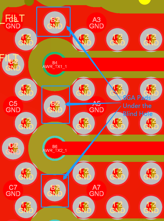
        As shown in the figure below, in the reference design of AWR2243, we found that semi-blind holes with L1-2 (in the blue box) were placed on the welding plate B3, B5 and B7.

        I have inquired the PCB board manufacturer about the design of laser perforation on the BGA welding plate, which would increase the manufacturing difficulty of THE PCB board, and even after processing into the finished product, the welding would be affected, causing virtual welding.I mean only for this "laser hole on the BGA solder pad" can you remove it?

    Thank you very much for your reply,

    -Robin

  • Hello Robin,

    As Randy mentioned the L1-L2 blind vias help provide the right impedance  to the RF transition and hence the best matching. Better impedance matching enables better RF performance. If these vias are removed there could be  larger impedance mismatch and hence impacting the RF performance.

    Regards,

    Vivek