This thread has been locked.

If you have a related question, please click the "Ask a related question" button in the top right corner. The newly created question will be automatically linked to this question.

IWR6843: SPI delay time

Part Number: IWR6843

Hello,

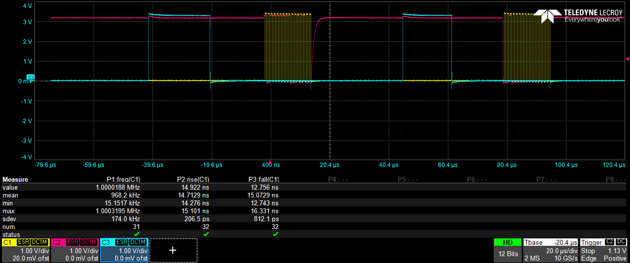
We use the SPIA interface to flash the IWR chip, however we have some problem with the stability (flashing doesnt work 100% of the time). I've done some timing measurement to see if there is a problem with the timing. We use the IWR6843 as Slave and and our CPU as master. The SPI interface is set up with Clock Polarity=0 and Clock Phase =0.

Our CKL frequency is 1MHz  (1us period time)

For SIMO I measure setup time to 997ns (6 in figure)

SIMO hold time is 998ns (7 in figure)

Both within spec.

For SOMI

I measure hold time to 506ns (5 in figure) within spec. Should be > 2ns

But the delay time is measured to 506ns (4 in figure) (clk rising to data faling/risning) this is out of your specification. According to you specification it should be <10ns. Se measurement plot below.

Do i misinterpret the specification or is the timing setup wrong?

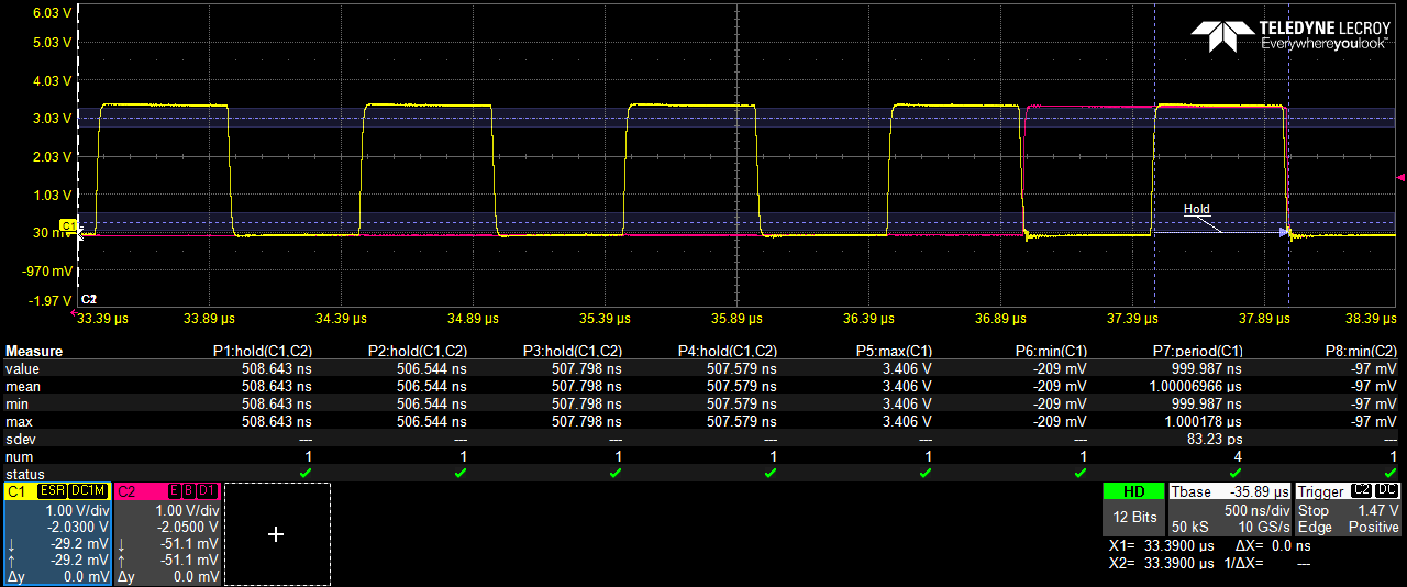
SOMI timing measurement

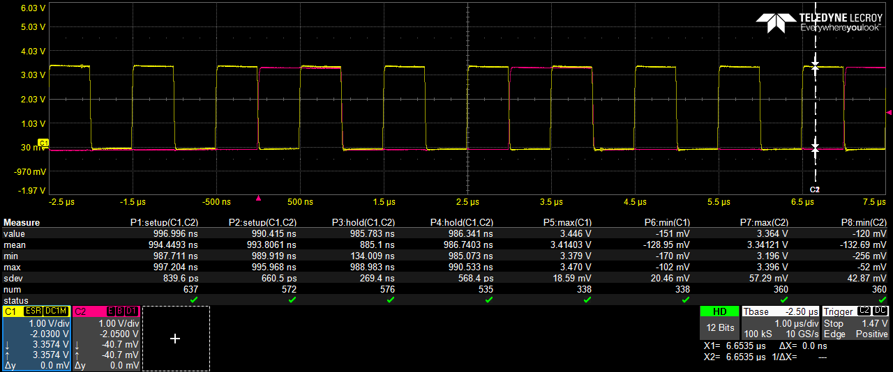
SIMO timing measurement

Best regards

Eagle Wang

  • Hello

    Can you please confirm that Flash type being used is one of the tested flash devices:  This would allow us to ensure device compatibility

    IWR6x43 Flash Variants Supported by the mmWave Sensor (Rev. B)

    For the flashing mechanism can you please suggest if the above questions for for QSPI interface - considering the flash device is connected to QSPI on the the mmwave devices.

    Thank you,

    Vaibhav

  • Hello,

    I do not use the QSPI flash. At boot we flash the IWR board directly to the IWR RAM memory from our main CPU.  This works like 70% of the time, but we want to get the stability up to 100%. Could you please check if there is a timing issue in the plots I've attached or if i have misinterpreted your specification.

    BR.

    Eagle

  • Hi,

    These are the few notes for SPI boot mode @C:\ti\mmwave_sdk_03_05_00_04\packages\ti\control\mmwavelink\docs\doxygen\html\index.html

    1. Host should ensure that there is a delay of at least 2 SPI clocks between CS going low and start of SPI clock.
    2. Host should ensure that CS is toggled for every 16 bits of transfer via SPI.
    3. There should be a delay of at least 2 SPI Clocks between consecutive CS.
    4. SPI needs to be operated at Mode 0 (Phase 1, Polarity 0).
    5. SPI word length should be 16 bit (Half word).

    Also: 

    1. It is recommended to use 232 as the chunk size in mmWavelink/HOST when firmware download is done through SPI. 

    Could you please confirm if above recommendations are met.

    Thanks

    Yogesh

  • Hello,

    Thank you for the reply,

    See my comments,  below.

    1. Host should ensure that there is a delay of at least 2 SPI clocks between CS going low and start of SPI clock.
      1. The delay between CS going low nad tstart of SPI clk is more than 2 SPI clock cycles
    2. Host should ensure that CS is toggled for every 16 bits of transfer via SPI.
      1. CS is toggeld every 16 bits
    3. There should be a delay of at least 2 SPI Clocks between consecutive CS.
      1. there is a delay of more than 2 SPI clocks between CS toggles
    4. SPI needs to be operated at Mode 0 (Phase 1, Polarity 0).
      1. Can you confirm that Mode 0 is Phase 1, Polarity 0? I've been taught that Mode 0 is Phase 0 and Pol 0.
    5. SPI word length should be 16 bit (Half word).
      1. We send the data in chunks of 16 bits.

    BR

    Eagle

  • Hi,

    Please refer to section 23.2.6.2 -Clocking Modes of the TRM https://www.ti.com/lit/ug/swru522e/swru522e.pdf

    Let us know if this help to improve the stability.

    Thanks

    Yogesh