Other Parts Discussed in Thread: IWR6843AOP
I am using mmwave studio to capture ADC raw data to do post processing in Matlab. I placed a corner reflector target in front of the radar, the range profile and range-doppler map all look good. However, I could not get any meaningful range-azimuth map from the recorded data. Here is what I did
This is the chirp config
profileCfg 0 60.75 7 7 41.10 0 0 54.71 1 96 2950.00 0 0 36
chirpCfg 0 0 0 0 0 0 0 1
chirpCfg 1 1 0 0 0 0 0 2
chirpCfg 2 2 0 0 0 0 0 4
frameCfg 0 2  96  0 50 1 0
I used mmWave Studio 2.1.1.0 to capture raw ADC data
I run rawDataReader('test.setup.json', 'test.mmwave.json', 'radarCube', 1) to generate the radar cube data
each frame of radar cube data is in format [n_chirps, n_rx, n_rangebins]
n_chirps actually is n_dopplerbins * n_tx
I assume the chirps are captured in this order c0_tx1, c0_tx2, c0_tx3, c1_tx1, c1_tx2, c1_tx3, ......, cn_tx1, cn_tx2, cn_tx3
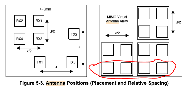
and based on the antenna position for IWR6843AoP shown below, i try to extract the chirps from the circled antennas, this is what i did
data1 = radar_cube_data(all cXX_tx1, rx4, :),
data2 = radar_cube_data(all cXX_tx1, rx3, :),
data3 = radar_cube_data(all cXX_tx3, rx4, :)
data4 = radar_cube_data(all cXX_tx3, rx3, :)
and use these chirps as returns from 4 linear antenna arrays to perform azimuth search using the Capon algorithm for each range bin. However, I could not get any meaningful range-azimuth map.
Is the chirp order I assume correct? Is there any Matlab post processing code that I can use to help generate range-azimuth map?
Also is there any phase rotation I need to apply to the captured data or when I generate the steering vector?