This thread has been locked.

If you have a related question, please click the "Ask a related question" button in the top right corner. The newly created question will be automatically linked to this question.

AWR2243: usage of Analog Test pins?

Part Number: AWR2243

Team, 

In the datasheets of our mmWave sensors there are several test & debug pins mentioned. But I couldn't find a description about how to use theses pins, what signals can be output, what can a customer do with this pins. I there any additional documentation available?

Thanks,
  Robert

  • Hi,

    The HW team will review this question and get back to you tomorrow

    thank you

    Cesar

  • Hello Robert,

    These pins are meant for TI  internal development and test purpose only. Not for customer usage. They are NC for practical purposes.

    Regards,
    Vivek 

  • Hello Vivek,

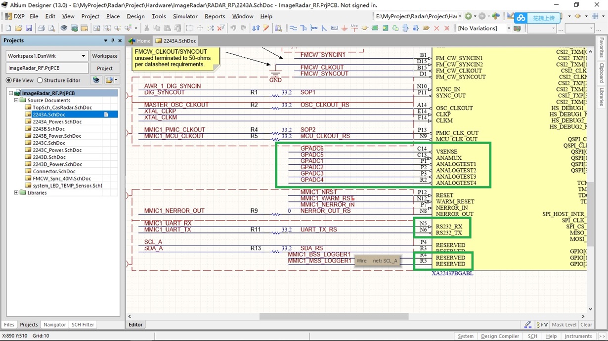
      In fact, I have same questions with Robert, confirm again: lists below in green rectangle, from my understanding belong to NC for customer? is it right?

  • Hello Simon,

    The C14,C13,P1/2/3,R2 are NC.

    The RX232 Rx/Tx and R4/R5 pins are recommended to be brought out on test points for debug in the datasheet. Incase customer faces issues on their platform TI can use these pins for some debug.

    Regards,
    Vivek

  • Hello Vivik,

       thanks so much!

       Another question: about JTAG of AWR2243, you still suggest we leave test points or connect FPGA I/O? from my view, it seems that customer can't use JTAG of AW2243, is it right?  in my solution, I use SPI/I2C to configure register of AWR2243, so I only leave QSPI to connect test points, is it ok?

    my solution is  4 pcs AWR2243+FPGA --cascaded, to save I/O of FPGA  and it is easy to do PCB layout, if pin is useless for customer, it is better to leave NC. 

       Appreciate for your good advice! 

  • Hello Vivek,

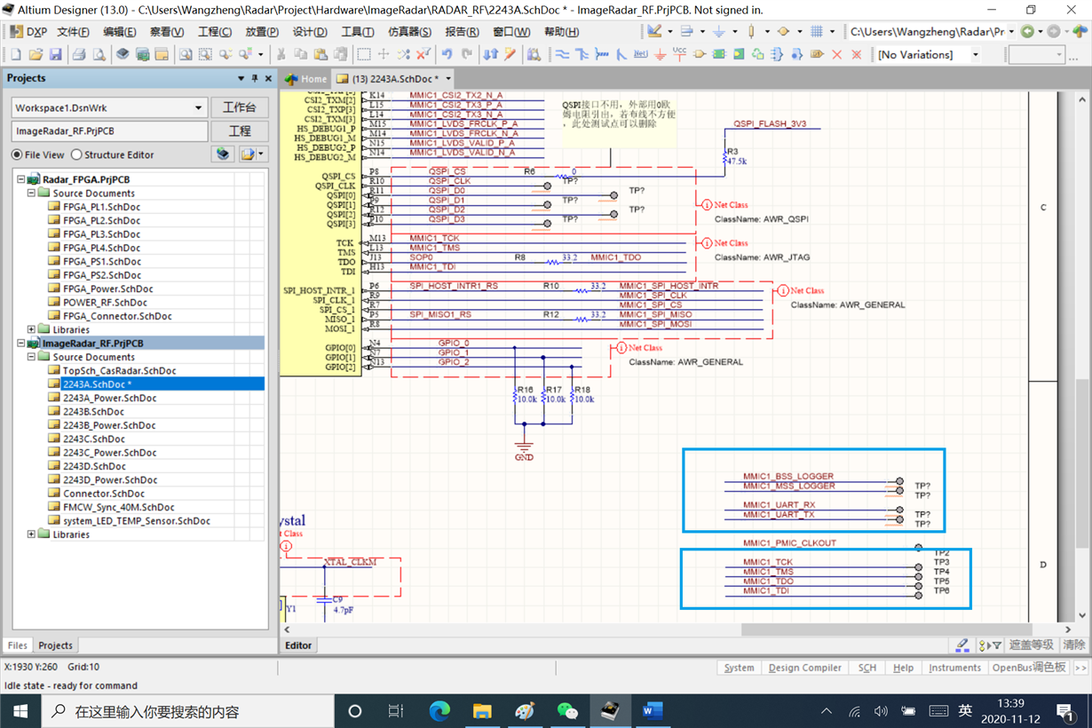
       now my product is 4D image radar and 4 pcs 2243+FPGA. your recommend is only to add test point for  RX232 Rx/Tx and R4/R5 pins or connect these pin to IO of FPGA for debug in the future. now my design is only to add test point. your comment is welcome!  JTAG is only to add test point.

      another quesiton: GPIO0~2, I know the three pin is I2C address, beside this function, recommend it to connect IO of FPGA? other function? thanks!

    blue rectangle!