This thread has been locked.

If you have a related question, please click the "Ask a related question" button in the top right corner. The newly created question will be automatically linked to this question.

IWR6843AOPEVM: ldoBypassEnable settings for EVM and lab code

Part Number: IWR6843AOPEVM

Hello Experts

So I am wondering about the SDK (3.5.0.4) and industrial toolbox (4.5.0) code that you provide and its compatibility with the IWR6843AOPEVM in terms of the LDO Bypass option of the chip.

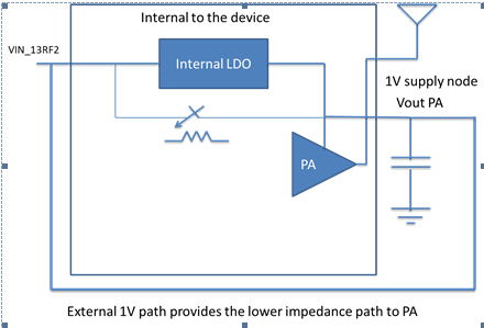
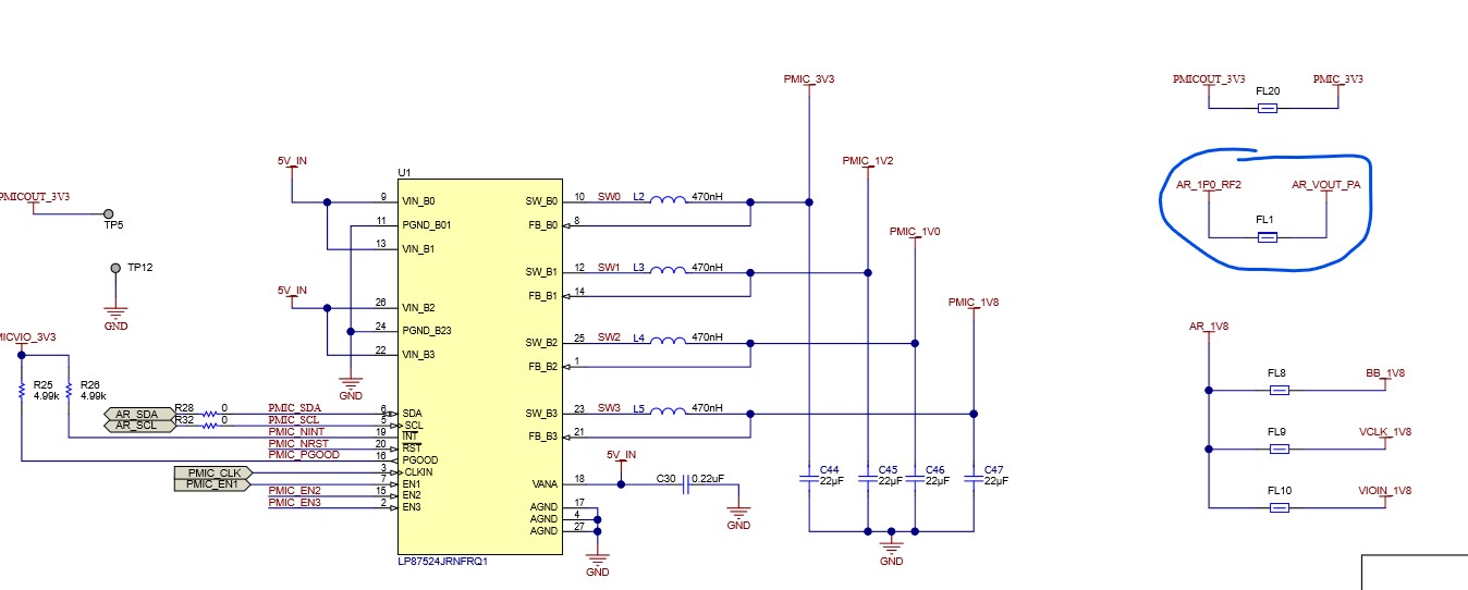
On the IWR6843AOPEVM the VIN_RFx is 1.0V and the Vout_PA voltage is shorted to the VIN_RF2 via ferrite bead.


So according to documentation and also in my opinion, the LDO bypass option should be enabled and the PA LDO input should be disabled, i.e. rlRfLdoBypassCfg_t.ldoBypassEnable set to 3. That is bit 0 set to 1 such that the RF LDO bypass is enabled (to be set when 1.0V RF supply is provided) and bit 1 set to 1 (PA LDO input disabled, to be used when VIN_RF is shorted to VOUT_PA) - (see definition and comments of rlRfLdoBypassCfg in mmwave_sdk_xx\packages\ti\control\mmwavelink\include\rl_sensor.h) defined here:

/*! \brief
* Radar RF LDO bypass enable/disable configuration
*/
typedef struct rlRfLdoBypassCfg
{
    /**
     * @brief  Enable LDO bypass \n
                [b0] 1: RF LDO bypassed, Should be used only when 1.0V RF supply is provided
                     0: RF LDO not bypassed(default), Should be used only when 1.3V RF supply
                     is provided \n
                [b1] 0: PA LDO input is enabled\n
                     1: PA LDO input is disabled (3 TX use case).
                        (To be used only when VIN_RF2 is shorted to VOUT_PA on board and VIN_RF2 is
                         1.0V) \n
                [b15:2] Reserved \n
                usecase                                            LDO bypass    PA LDO disable \n
                1.3V RF supply 1 and 1.3V RF supply 2                 0               0
                1.0V RF supply 1 and 1.0V RF supply 2                 1               0
                1.0V RF supply 1 and 1.0V RF supply 2                 1               1
                     and RF supply 1 shorted to Vout PA

     */
    rlUInt16_t ldoBypassEnable;
#ifndef MMWL_BIG_ENDIAN
    /**
     * @brief  IR drop is the voltage drop from the PMIC output to the device pin. The user
               should program the voltage drop in percentage units which will be used for
               measuring the external supplies.  \n
                Value  Description   \n
                0      IR drop of 0% \n
                1      IR drop of 3% \n
                2      IR drop of 6% \n
                3      IR drop of 9% \n
     */
    rlUInt8_t supplyMonIrDrop;
    /**
     * @brief  IO supply indicator. This is used to indicate the IO supply to the MMIC device
     *         for setting the correct voltage monitor thresholds
     *         Value   Description \n
     *          0      3.3 V IO supply \n
     *          1      1.8 V IO supply \n
     */
    rlUInt8_t ioSupplyIndicator;
 // etc...
}rlRfLdoBypassCfg_t;

Now, in all code examples provided, including the out of box demo to be used with the IWR6843AOPEVM (mmwave_sdk_xxx\packages\ti\demo\xwr68xx\mmw\ and mmwave_industrial_toolbox_yyy\labs) usually in the mss_main.c file there is a section:

rlRfLdoBypassCfg_t gRFLdoBypassCfg =
{
    .ldoBypassEnable   = 0, /* 1.0V RF supply 1 and 1.0V RF supply 2 */
    .supplyMonIrDrop   = 0, /* IR drop of 3% */
    .ioSupplyIndicator = 0, /* 3.3 V IO supply */
};

Now the comments on this seem to be wrong:
- supplyMonIrDrop = 0 would mean monitor is allowing 0% of IR drop, contrary to the comment which states 3%
- ldoBypassEnable = 0 would mean rf ldo is not bypassed and pa ldo is enabled, contrary to the code comment and contrary to the hardware schematic of the board to run the code on (IWR6843AOPEVM)

Shouldn't this be:

rlRfLdoBypassCfg_t gRFLdoBypassCfg =
{
    .ldoBypassEnable   = 3, /* 1.0V RF supply 1 and 1.0V RF supply 2 */
    .supplyMonIrDrop   = 1, /* IR drop of 3% */
    .ioSupplyIndicator = 0, /* 3.3 V IO supply */
};

So I am confused in several ways:

- why does the code run on the IWR6843AOPEVM even though it is likely wrong?
- what are the correct values to set for my board (we have the same supply structure as the IWR6843AOPEVM) for best performance
- which comments are correct in the code, the ones in the example projects or the one in the mmwavelink API?
- Plus: what are the default values on startup and why do not all lab projects have the ldo set up in their code? (example: industrial toolbox\labs\people_counting\overhead_3d_people_counting does not set the LDOBypass, while int the same lab people_counting\68xx_3D_people_counting\ does set the ldo [but apparently wrongly]=?

  • Hello,

     Below is the scheme for the internal LDO. 


    On the EVM hardware we AR_1P0_RF2 shorted to AR_VOUT_PA, Hence PA power is supplied through external supply irrespective of LDO is bypassed or not in 1V mode. Hence it's working on all the demo codes.

    If the design is such that 1.3V is fed then this below short should be removed and internal LDO must be enabled to get 1V supply on the PA. 

    Thanks and regards,

    CHETHAN KUMAR Y.B.

  • Hi Chethan

    Yes - thats exactly what I mean. RF2 is shorted to Vout _PA

    Now in the code however the setting is

    .ldoBypassEnable   = 0, /* 1.0V RF supply 1 and 1.0V RF supply 2 */

    which would mean that A) LDO is enabled (which is useless if PA is powered by external input), but B) PA is powered by LDO (bit[1]) instead of selecting it to be powered by V_PA. This basically means you agree with me that the code should be either

    .ldoBypassEnable   = 3, /* 1.0V RF supply 1 and 1.0V RF supply 2 */

    (equal to LDO=off, PAPower=external) or at least

    .ldoBypassEnable   = 2, /* 1.0V RF supply 1 and 1.0V RF supply 2 */

    (equal to LDO=On, PAPower=external)

    and not

    .ldoBypassEnable   = 0, /* 1.0V RF supply 1 and 1.0V RF supply 2 */

    (as it is in all the projects...)

    So you agree its all wrong?

    The Eval boards have a 1.0V output and not 1.3V

  • not resolved / nor answered the question but just pointed out what has been said before

  • Hello,

         Confirming on the board it uses 1.0V external supply for the RF rail. On the firmware settings need to consult with our software/firmware team. Allow couple of days to check on this.

    Thanks and regard,

    CHETHAN KUMAR Y.B.

  • Hello,

    Thanks for your patience and bringing this out. From the hardware description provided by Chethan, your analysis for ldoBypass configuration on AOPEVM seems to be correct but we still need to confirm with our device and SDK team on this. Please allow us a few more days to get a confirmation.

    Regards

    -Nitin

  • Hello,

    I confirmed with our device team and your values for ldoBypass and supplyMonIrdrop are correct for the xWR6843AOP EVM.

    rlRfLdoBypassCfg_t gRFLdoBypassCfg =
    {
        .ldoBypassEnable   = 3, /* 1.0V RF supply 1 and 1.0V RF supply 2 */
        .supplyMonIrDrop   = 1, /* IR drop of 3% */
        .ioSupplyIndicator = 0, /* 3.3 V IO supply */
    };
    The SDK code has kept it at default with the bypass disabled and PA LDO enabled and the documentation mentions to refer to the EVM user guide in case any changes are needed. However, there is scope for improvement in that the SDK example should select appropriate configuration for the underlying TI EVM that it is running on. Thanks for bringing this to our notice. We will take this feedback to improve the SDK examples.
    Regards
    -Nitin