This thread has been locked.

If you have a related question, please click the "Ask a related question" button in the top right corner. The newly created question will be automatically linked to this question.

LM94022-Q1: EMI rectified into a DC offset??

Part Number: LM94022-Q1

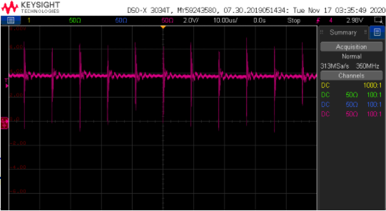
I have an application where I have a LM94022-Q1 mounted on a board that carries phasing currents for a motor. The board is potted into the motor and I am using this sensor to get temperature data. When the motor is energized (the drive starts switching), the sensor's output shows a DC jump (as confirmed by a scope reading the sensor's output directly) of about 1V which invalidates all the temperature data. This DC offset increases with increasing bus voltage (motor bus voltage can vary between 40V and 100V). 

The temp sensor itself receives +5V power and is locally decoupled with a 0.1uF capacitor. There is a 1uF cap at the power connector to this board. No other components exist on this board (just a bunch of internal layers for routing the HV signals). Due to layer utilization the layer just underneath the temp sensor is a switching node (containing the 40-100V bus voltage) however the ground return for the LM94022-Q1 is ran on the same side of the board as the chip (as well as +5V power and signal). So the layout here could be a little better to add the reference plane underneath the temp sensor IC. 

Anyway, I was expecting to run into EMI and my plan was to just filter out the AC components at the data acquisition board. However it looks like the EMI is causing a DC offset in the output. Is this a thing with diode based temperature sensors? Has anyone run into this before? Are there components out there that are more immune than the LM94022-Q1?

Thanks.

Matt

  • Hi Matt,

    I can't say that I've seen EMI issues cause a DC offset with one of our temperature sensors before. Do you mind showing a scope shot of the sensor output along with the switching motor voltage? Does the DC offset occur persist indefinitely or only at the moment of the switching input? 

    Jalen

  • Below are scope shots of the sensor's output. Shown on the left is sensor output a little over 2V (reading is around 20C). Shown on the right is the sensor's output when the motor starts receiving voltage (no current yet, just switched DC voltage @ 70V @ ~100kHz. As you can see the DC component has been boosted about 1V.

    The DC offset exists as long as the motor drive is enabled and the motor is receiving switched voltage. Here's a zoomed in version of the plot on the right:

    To be fair, this sensor is about 1mm away from the motor coils (airgapped by some thermal epoxy). I don't have a scope shot of the sensor's supply rail saved but it is a pretty solid 5V.

  • Matt,

    I think it is clear that the high current is causing this GND offset. Does this offset exist on the GND of the motor supply at other test points?

    In layout is the GND from the temp sensor sharing from your data acquisition board? You may need to separate your analog and digital GND due to this problem. Otherwise, in high EMI environments using a twisted pair of shielded cables can help eliminate the offset you see.

    Jalen