This thread has been locked.

If you have a related question, please click the "Ask a related question" button in the top right corner. The newly created question will be automatically linked to this question.

LDC0851: Design of Target wheel and inductive sensors PCB required for three phase output

Part Number: LDC0851
Other Parts Discussed in Thread: LDC1314, LDC1312,

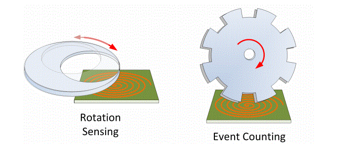
I am looking for a three phase output from a LDC0851/LDC1312/LDC1314 Inductance to Digital converter. The output should mimic Hall Effect Sensor digital output with phase shifted waveforms typically designated as H1, H2 and H3. A design for Target wheel and Sensors PCB would be appreciated.

Thanks in advance for your time.

Regards,

Hemant

  • Hemant,

    A three phase configuration with inductive sensing is an interesting concept.  I'm not aware of any existing design I can provide you as a reference for this type of solution.

    A three phase output requires the sensors to be spaced 120 degrees electrically.  Ideally, we would see a 50% duty cycle from each device.  A few options might be worth considering for this design.  It may be possible to use a target shape similar to what is shown on the left.  Here we will vary the size of the target material in a fairly sinusoidal manner.  If this is too unbalanced for your system, it may make more sense to use a shape similar to what is on the right.  With a gear tooth pattern, we can produce alternating regions for the sensors to detect.  The number of teeth will impact the resulting output frequency from the three devices.  For instance a tooth size of 60 degrees will result in a 3x increase in output frequency.