This thread has been locked.

If you have a related question, please click the "Ask a related question" button in the top right corner. The newly created question will be automatically linked to this question.

IWR6843ISK-ODS: Clarifications on slow time processing principles

Part Number: IWR6843ISK-ODS
Other Parts Discussed in Thread: IWR6843

Hello TI team,

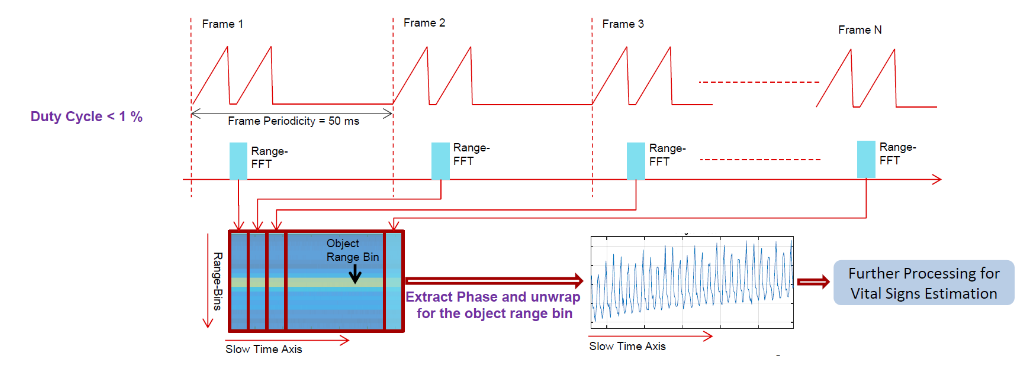
I've been looking into an idea of "slow-time" data processing. It is described in the vital signs lab, and here is the screenshot that explains it in a nutshell:

I'm interested in applying this principle but for point cloud data generation (not vital signs detection). I'd like to be able to detect a very slow movement, about 0.5-5 cm/sec and this approach seems potentially capable since it still allows to use higher-FPS chirp config. I have developed a somewhat working prototype in Matlab, and I'm using raw data captures that were recorded by using your board DCA1000. The chirp config that I used for data captures had framerate of 16 FPS.

My question is about maximum velocity for the slow-data-processing and whether there are ways to increase it for the slow-time processing. Currently, the slow-time algorithm follows:

  • Sample 1st range-FFT for each frame - collect frames for 1000 msec, thus in total I have 16 range-FFTs and I treat this as a slow-time frame.
  • Process the slow-time frames and extract necessary info (point cloud data in my case).

With this setup I am able to achieve maximum velocity of about 0.02 m/s.

It is calculated as follows: v_max = lambda / (4 * T_chirp), and T_chirp = 62.5 msec (timing between each consecutive frames).

In order to increase the max velocity value, at first I though I could just sample range-FFTs within fast frames, for example, take every 4th frame and add them all to stack - and do it during 1000 msec. But I was getting some strange-looking range-Doppler heatmaps with such arrangement. And then I realized that it is probably due to the fact that fast-times rangeFFTs are not distributed evenly, and that there is a silent time when DSP work is done. Something like this:

///////////////////--------DSP time-----///////////////////--------DSP time-----///////////////////--------DSP time-----///////////////////--------DSP time-----...

Could you confirm this, please?

So I cannot sample, let's say, every 4th range-FFT for 16 frames for slow-data processing, because then the idle time will not be even for my slow-time frames stack. The sampled range-FFTs would be separated by larger idle times, however I would like to be able to treat them as range-FFTs for one frame:

////           ////            ////             //// ...

I was wondering if you could provide any advise on this? Is there a way to compensate for the "DSP time" when I calculate the range-Doppler heatmap for slow-time processing when selecting every 4th range-FFT? Or is it impossible in theory and I can only get v_max=0.02m/s for 16 FPS with the slow-time data being sampled once per fast-time frame? I need to keep the original point cloud data DSP, so I cannot remove that part from the firmware.

  • Thank you.

    Best regards,

    Victoria

  • Hi Victoria

    If I understand correctly, the user is collecting raw ADC data using the DCA board and wants to process every 4th chirp from a given frame.

    The users interpretation is correct that the range-Doppler heat-map will look strange due to non-uniform sampling between the chirps across the frames. However the “DSP time” that the user is mentioning is not applicable here as user is collecting raw ADC data hence there is NO DSP processing time in between the frames.


    What’s happening is that user’s inter-chirp interval (T1) within the frame is smaller than the inter-chirp interval (T2) at the frame boundaries as illustrated in the figure below. As the FFT assumes uniform sampling the heat-map would not look correct in this case.


    There could be a couple of potential ways to deal with it. Some could be

    (a)    Adjust the inter-chirp idle time and frame periodicity to make the inter-chirp intervals between the chirps within the frame and across the frames uniform :Depending on the user requirements this might or might not be feasible

    (b)   Acquire a single large duration frame : This will guarantee that the chirp intervals are uniformly sampled. Sampling interval will be equal to the inter-chirp interval

    (c)    Process a single chirp within a frame  : This will guarantee that the chirp intervals are uniformly sampled. Sampling interval will be equal to the frame periodicity. This is what is done in the vital signs Lab

    (d)   FFT  assumes that the data is uniformly sampled. One way is to insert zero’s for each of the missing timing intervals (between chirp 4 and 5 in the figure above). The number of zeros to insert would depend on the chosen inter-chirp interval and frame periodicity.   


    As a start, I would suggest exploring option (d) and see if the heat-maps look any better (quality would depend on the number of zero insertions required).

    Regards,

    AG

  • Hello Akash,

    Thank you for your full reply. Could you please re-upload the figure? I cannot see it. I had to re-upload mine using the editing interface, dropping it directly does not make it show up.

    Also couple follow-up questions, if you don't mind:

    • The end goal is to implement the slow-time processing as a part of firmware (the raw data collected by ADC1000 is only a prototype to proof the concept) - would the "DSP time" concept apply for when we consider running the algorithm as part of FW on the board? For example, if I have a chirp config with duty cycle 30%, that means the 70% of time is the DSP/silent time, right?
    • Thus, regarding option (d) that you described in your answer, if I was to implement it as a part of firmware to run on IWR6843, the number of padded zeros would not be the same as for my Matlab prototype/raw data? And it would likely increase, is that right? Considering all that, it may be difficult to use this method in practice, directly on IWR6843 - what do you think? since the time interval seems to be so much larger.

    Thank you.

    Best regards,

    Victoria