Other Parts Discussed in Thread: LDC1612, LDC1614, LDC1314
I am currently trying to measure the self-inductance of a coil using LDC1614EVM for a research project in which we use Arduino to control the entire system.
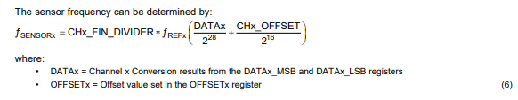
I found an LDC1612/1614 driver library for Arduino and tried it as is. Although it worked, it does not seem to be returning the inductance value. The self-inductance of this coil is around 2[µH] but the numbers I receive are around 149*10^6.
I’m assuming this output value is the frequency that LDC1614 receives from the coil.
The code I’m using is below. Could you possibly have a look at this code and figure out how to translate the output value into inductance? Or if you could provide me other libraries that potentially work the way I want, that would be greatly appreciated too.
For your reference, this library is from here.
/**
******************************************************************************
* File Name : LDC1614_example
* Description : Example program for LDC16xx_lib
******************************************************************************
*
* Copyright (c) 2018 CNR-STIIMA DASM Group
* All rights reserved.
*
* Redistribution and use in source and binary forms, with or without modification,
* are permitted provided that the following conditions are met:
*
* 1. Redistributions of source code must retain the above copyright notice,
* this list of conditions and the following disclaimer.
* 2. Redistributions in binary form must reproduce the above copyright notice,
* this list of conditions and the following disclaimer in the documentation
* and/or other materials provided with the distribution.
* 3. The name of the author may not be used to endorse or promote products
* derived from this software without specific prior written permission.
*
* THIS SOFTWARE IS PROVIDED BY THE AUTHOR ``AS IS'' AND ANY EXPRESS OR IMPLIED
* WARRANTIES, INCLUDING, BUT NOT LIMITED TO, THE IMPLIED WARRANTIES OF
* MERCHANTABILITY AND FITNESS FOR A PARTICULAR PURPOSE ARE DISCLAIMED. IN NO EVENT
* SHALL THE AUTHOR BE LIABLE FOR ANY DIRECT, INDIRECT, INCIDENTAL, SPECIAL,
* EXEMPLARY, OR CONSEQUENTIAL DAMAGES (INCLUDING, BUT NOT LIMITED TO, PROCUREMENT
* OF SUBSTITUTE GOODS OR SERVICES; LOSS OF USE, DATA, OR PROFITS; OR BUSINESS
* INTERRUPTION) HOWEVER CAUSED AND ON ANY THEORY OF LIABILITY, WHETHER IN
* CONTRACT, STRICT LIABILITY, OR TORT (INCLUDING NEGLIGENCE OR OTHERWISE) ARISING
* IN ANY WAY OUT OF THE USE OF THIS SOFTWARE, EVEN IF ADVISED OF THE POSSIBILITY
* OF SUCH DAMAGE.
*
* Credits go to Jeremi Wójcicki (and the current maintainers) of this software.
*
**/
#include "LDC16xx_lib.h"
// user selecatable comppile option
// 0 - use user polling to read sensor data
// 1 - use syncronized sensor read with INTB pin interrupt
#define IRQ_HANDLER 0
// single channel conversion setup with disabled INTB by default
LDC_configReg default_config[] = {
{ LDC16xx_MUX_CONFIG, LDC16xx_BITS_DEGLITCH_3_3Mhz },
{ LDC16xx_CONFIG, LDC16xx_BITS_ACTIVE_CHAN_CH0 | LDC16xx_BITS_AUTO_AMP_DIS | LDC16xx_BITS_INTB_DIS },
{ LDC16xx_SETTLECOUNT_CH0, 0x0050 },
{ LDC16xx_RCOUNT_CH0, 0xffff },
};
#define LDC_CONFIG_SIZE sizeof(default_config)/sizeof(LDC_configReg)
// global sensor object pointer
LDC16xx *ldc;
// an ISR control flag for pending sensor data
volatile bool drdy = 0;
// interrupt service routine - when sensor conversion is complete
// this code should be light not to block the main loop for too long
void onDataReady(){
drdy = true;
}
void setup() {
// put your setup code here, to run once:
Serial.begin(115200);
Serial.println("Starting execution ...");
// create a new LDC sensor object, initialize interface
// I2C clock of 100kHz or 400kHz is allowed
ldc = new LDC16xx(Wire, 400000);
// verify chip ID. On fail halt program
uint16_t id, manuf;
ldc->readRegister(LDC16xx_DEVICE_ID, &id);
ldc->readRegister(LDC16xx_MANUFACTURER_ID, &manuf);
Serial.print("Chip ID: 0x");
Serial.println(id, HEX);
Serial.print("Manufacturer ID: 0x");
Serial.println(manuf,HEX);
if(id == LCD16xx_DEFAULT_DEVICE_ID && manuf == LDC16xx_DEFAULT_MANUFACTURER_ID){
Serial.println("Verification OK");
} else {
Serial.println("Wrong chip or manufacturer ID, stopping execution...");
while(1);
}
// reset device wiping previous configuration
ldc->resetDevice();
// load our config
ldc->loadConfig(default_config, LDC_CONFIG_SIZE);
#if IRQ_HANDLER == 1
// attach IRQ and set appropriate LDC registers to enable INTB interrupt
// depending on used board consult www.arduino.cc/.../ for possible pin configurations
// user pin 2 for INTB
ldc->enableDataReadyInterrupt(2, onDataReady);
#endif
// for debug, dump values of all register to the console
ldc->registerDump(Serial);
}
// main loop
void loop() {
#if IRQ_HANDLER == 1
while(!drdy);
drdy = false;
#endif
uint32_t data;
uint16_t status;
// read the channel no 0. data
ldc->readChannel(0, &data);
#if IRQ_HANDLER == 1
// in IRQ mode status must be read to re-enable conversion and re-assert INTB
ldc->readRegister(LDC16xx_STATUS, &status);
#endif
// print read data in the console
Serial.println(data, DEC);
#if IRQ_HANDLER == 0
// we time the loop by ourselves (optionally we could ask the chip periodically for status)
// ideally you should make sure we are syncronized with sensor conversion rate (RCOUNT + clock source)
delay(24); // ~41.5 sps
#endif
}