This thread has been locked.

If you have a related question, please click the "Ask a related question" button in the top right corner. The newly created question will be automatically linked to this question.

TMAG5170-Q1: Properly configuring registers

Part Number: TMAG5170-Q1

I am working on getting the TMAG5170-Q1 up and running and am struggling to get readings. At this point I am suspecting that I am not configuring it properly, so wanted to ask if I am doing everything necessary to read from X, Y, and Z below:

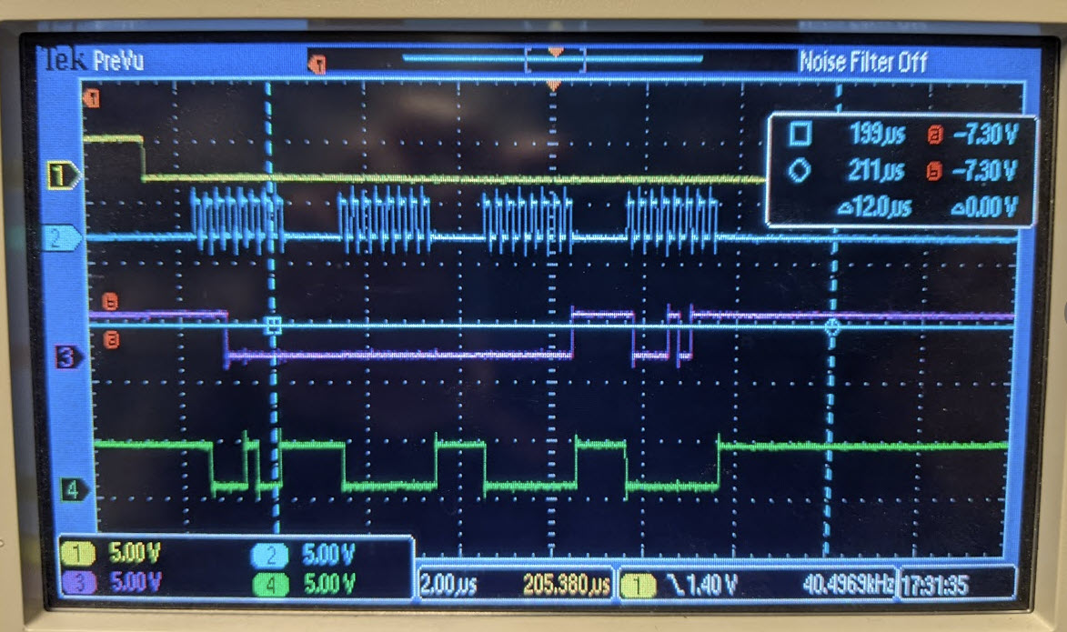
I am sending the 32 bits in 4x byte long increments, starting with the address, then 1/2 data, 1/2 data, and ending with command and CRC in one byte. The first thing I am doing is disabling CRC as per the write found in other posts on the forum, and from there I send all 0's for command and CRC.

Two configs I am unsure of are: do I need to be in active running mode? And do I want to configure MAG_CH_EN as 0x7 = X, Y, Z channel enabled, or  0x8 = XYX channel enabled?

For configuring I am doing the following:

writeRegister(0x04, 0x00, 0x04, 0x07); // from TI support - write a 0x0F000407 which disables CRC in the test config address e2e.ti.com/.../937812
writeRegister(0x01, 0b00011001, 0b11101010, 0x00); //0x1 = SENSOR_CONFIG: Configure X,Y, and Z RANGE to be +/-100mT + activate readings on all axes (they default to off)
writeRegister(0x00, 0b00100001, 0b00100000, 0x00); // 0x0 = DEVICE_CONFIG: Set to 4x averaging + ND temp coefficient + set to active measure mode + disable temp stuff

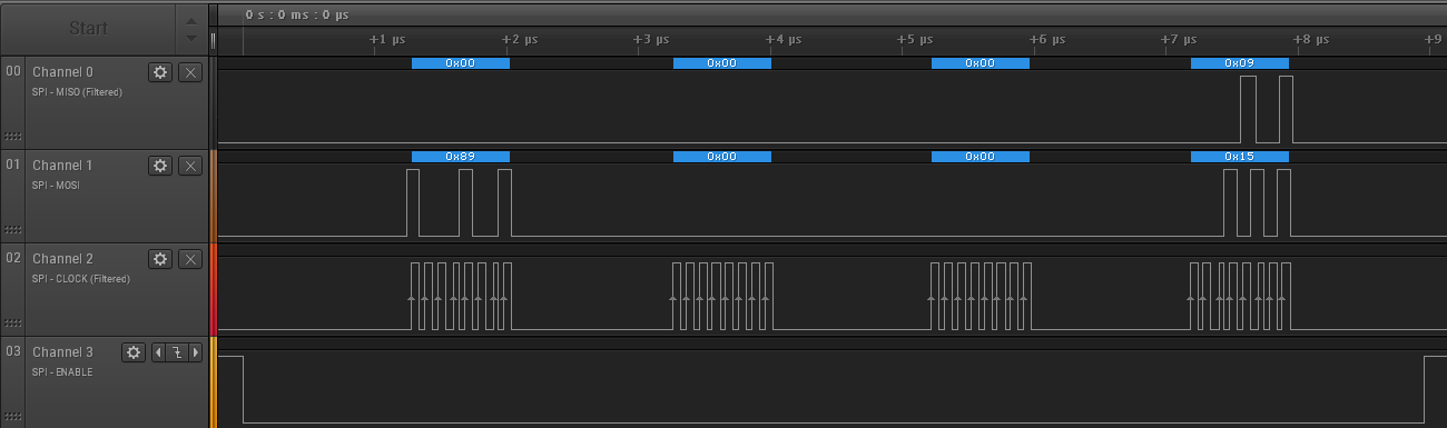
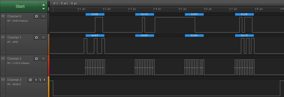
For reading I am doing the following, sending all 0's after the address:

readRegister(0x89,0x00,0x00,0x00); // read X_CH_RESULT

Does anything look amiss here? Thanks in advance!

  • David,

    Your first write to disable CRC looks like it does not match the command that you found and referred to.  The first 8 bits define the register.  It appears in your code that you are writing to register 0x04 instead of 0x0F.  I would expect after you change this that you should be able to get it operational.

    It looks like your subsequent writes match the comments, and these should correctly set the device to start monitoring on X,Y,and Z within the +/-100 mT range.

    With the device configured this way, you should be able to read register 0x09 for the X channel data.

    XYZ mode will enable all three channels for conversions.  Depending on how the magnet is presented to the sensor you may or may not need all three inputs.  If you are only interested in the X and Y channels, you could produce the fastest conversions possible by selecting only these channels.  XYX mode adds a second X conversion that will approximate X as if it were sampled simultaneous to Y.  This helps in systems where the magnet is moving and angular calculations are being made.

    Thanks,

    Scott

  • Hi Scott,

    Thanks for the fast reply, and apologies for that simple mistake which I've corrected!

    Unfortunately I am still not getting any readings in the data phase. I scoped my setup in the attachment you can see CS, SCLK, MISO, and MOSI in descending order. I am getting nothing in the dataphase and a 0b1000 in status 0-3 and 0b1011 in CRC. I get this regardless of what I send on MOSI.

    I double checked my wiring +bypass cap which look fine, although I am not pulling up Alert which seemed fine from the datasheet?

  • Alert should be okay without the pull up, assuming you will not be using it as an output.

    From this scope capture I see the CRC Status and Error status bits are high.  These should be low on the very first transaction.

    Also, it looks like your MOSI command is x8980 0000.  The data bits shouldn't matter, but I do notice that this does not match your input command. It may be worth checking your write commands to see that they match the expected values. 

    As a reference, here is what I capture on my EVM for the same transactions you are attempting.

    Output Disabled

    Output Enabled

    Also, to help debug, here are each of the commands you shared from above with their respective CRC code.  I would suggest you attempt these commands to debug and verify that all inputs match as expected.

    Disable CRC

    0x0F00 0407

    Sensor Config

    0x0119 EA0E

    Device Config

    0x0021 200C

    Read X

    0x8900 0015 or 0x8900 0000

    Read Y

    0x8A00 0011 or 0x8A00 0004

    Read Z

    0x8B00 001C or 0x8B00 0009

  • Hey Scott, thanks so much for all of your guidance here, I am up and running now (still not 100% sure what I had wrong there but I rewrote my write and read commands and got it working). Hope you had a great holiday, and thanks again for the excellent support.