This thread has been locked.

If you have a related question, please click the "Ask a related question" button in the top right corner. The newly created question will be automatically linked to this question.

IWR6843AOPEVM: Max range in visualizer tool for people counting labs

Part Number: IWR6843AOPEVM
Other Parts Discussed in Thread: IWR6843

Hello,

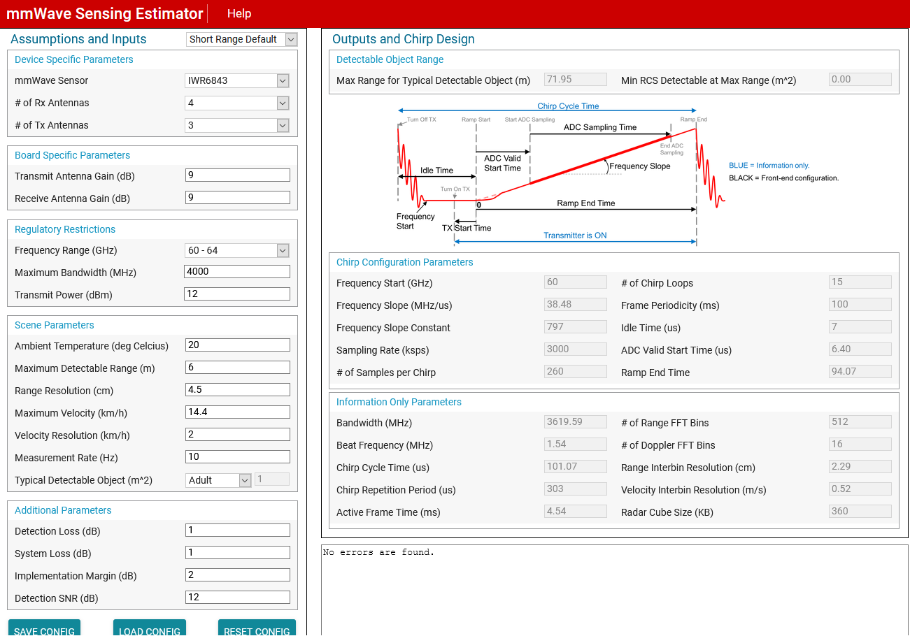
I'm testing the IWR6843AOPEVM performance using the lab called "68xx_3D_people_counting" and the "visualizer" tool ( mmWave_People_Counting_GUI.exe) provided by the "mmwave_industrial_toolbox_4_5_1__win" package.

Following is my custom configuration file loads in the visualizer:

*********************************

sensorStop
flushCfg
dfeDataOutputMode 1
channelCfg 15 7 0
adcCfg 2 1
adcbufCfg -1 0 1 1 1
lowPower 0 0
profileCfg 0 60 80 7 27 0 0 120 1 250 12500 0 0 30
chirpCfg 0 0 0 0 0 0 0 1
chirpCfg 1 1 0 0 0 0 0 2
chirpCfg 2 2 0 0 0 0 0 4
frameCfg 0 2 128 0 41.388 1 0
dynamicRACfarCfg -1 4 4 2 4 8 16 4 4 4.00 4.50 0.50 1 1
staticRACfarCfg -1 4 4 2 4 8 16 4 6 12.00 13.00 0.30 0 0
dynamicRangeAngleCfg -1 0.75 0.0010 1 0
dynamic2DAngleCfg -1 1.5 0.0300 1 0 1 0.50 0.85 8.00
staticRangeAngleCfg -1 1 8 4
antGeometry0 -1 -1 0 0 -3 -3 -2 -2 -1 -1 0 0
antGeometry1 -1 0 -1 0 -3 -2 -3 -2 -3 -2 -3 -2
antPhaseRot 1 -1 1 -1 1 -1 1 -1 1 -1 1 -1
fovCfg -1 70.0 20.0
compRangeBiasAndRxChanPhase 0 1 0 1 0 1 0 1 0 1 0 1 0 1 0 1 0 1 0 1 0 1 0 1 0
staticBoundaryBox -1 2 2 5 -1.1 2
boundaryBox -1.5 2.5 0.3 6 -1.1 2.5
sensorPosition 1.1 0 0
gatingParam 3 2 2 2 0
stateParam 3 3 10 40 5
allocationParam 0 800 0.1 15 0.1 20
trackingCfg 1 2 1000 20 67 105 41.388
sensorStart

************************************

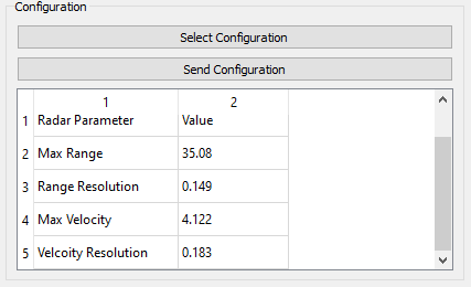
The visualizer calcs a Max Range equal to 14.06 m.

Using the following theorical formula for FMCW radar I get:

Max Range =  ( Fs * Tc * c ) / ( 4 * B ) = 7.8125 m  <<<<<< DIFFERENT VALUE


Where:

  • Fs = ADC Sampling Frequency (ksps) = 12500000 complex_sample / sec
  • Tc = ADC Sampling time = Num ADC Samples / Fs = 20 usec

  • c = light velocity = 3 *10^8 m/sec

  • B = Bandwidth = Frequency Slope * Tc = 2.4GHz

I highlighted with the same color the values usaed in the calcs and reported in the configuration file.

What is it wrong?

Regards,

Lorenzo

  • Hello

    Please note a few things

    1. Each demo and config file are made in tandem and although in theory you can change the radar sensing parameters to values acceptable to device the demo code may be created with certain sensing assumptions that you may be violating

    So in short please do not expect demos to work while you change parameters.

    If you wish to change parameters please look at the customization guide provided  specific to the  demo and or understand the implementation and assumptions made in the demo

    2. For basic fmcw parameters changes - Please use the out of box demo and chirp estimator to flush the working  and processing needs then move to other demos.

    So for the changes in. Question please try these on 'out of box' demo and get them working there then people counting specific issues can be addressed

    Hope this helps

    We will provide follow up to this thread next week.

    Please respond  next week if you do not see a response.

    Thank you

    Vaibhav

  • Hi Vaibhav,

    I tried to use the online "mmWave Sensing Estimator" tool ( https://dev.ti.com/gallery/view/1792614/mmWaveSensingEstimator/ver/1.3.0/ ).
    Following you can find the screenshot with the parameters set

    and following the file IWR6843.estimator.mmwave.json exported:

    ***************************

    {
        "configGenerator": {
            "createdBy": "mmWaveSensingEstimator",
            "createdOn": "2020-11-26T09:54:01.464Z",
            "isConfigIntermediate": 0
        },
        "currentVersion": {
            "jsonCfgVersion": {
                "major": 0,
                "minor": 4,
                "patch": 0
            },
            "DFPVersion": {
                "major": 1,
                "minor": 2,
                "patch": 0
            },
            "SDKVersion": {
                "major": 3,
                "minor": 0,
                "patch": 0
            },
            "mmwavelinkVersion": {
                "major": 1,
                "minor": 2,
                "patch": 0
            }
        },
        "lastBackwardCompatibleVersion": {
            "DFPVersion": {
                "major": 1,
                "minor": 1,
                "patch": 0
            },
            "SDKVersion": {
                "major": 2,
                "minor": 0,
                "patch": 0
            },
            "mmwavelinkVersion": {
                "major": 1,
                "minor": 1,
                "patch": 0
            }
        },
        "systemConfig": {
            "summary": "",
            "sceneParameters": {
                "ambientTemperature_degC": 20,
                "maxDetectableRange_m": 6,
                "rangeResolution_cm": 4.5,
                "maxVelocity_kmph": 14.4,
                "velocityResolution_kmph": 2,
                "measurementRate": 10,
                "typicalDetectedObjectRCS": 1
            }
        },
        "regulatoryRestrictions": {
            "frequencyRangeBegin_GHz": 77,
            "frequencyRangeEnd_GHz": 81,
            "maxBandwidthAllowed_MHz": 4000,
            "maxTransmitPowerAllowed_dBm": 12
        },
        "processingChainConfig": {
            "detectionChain": {
                "name": "",
                "detectionLoss": 1,
                "systemLoss": 1,
                "implementationMargin": 2,
                "detectionSNR": 12,
                "theoreticalRxAntennaGain": 9,
                "theoreticalTxAntennaGain": 9
            }
        },
        "mmWaveDevices": [
            {
                "mmWaveDeviceId": 0,
                "rfConfig": {
                    "summary": "",
                    "waveformType": "singleFrameChirp",
                    "MIMOScheme": "TDM",
                    "rlChanCfg_t": {
                        "rxChannelEn": "0xF",
                        "txChannelEn": "0x7"
                    },
                    "rlAdcOutCfg_t": {
                        "fmt": {
                            "b2AdcBits": 2,
                            "b8FullScaleReducFctr": 0,
                            "b2AdcOutFmt": 2
                        }
                    },
                    "rlLowPowerModeCfg_t": {},
                    "rlProfiles": [
                        {
                            "rlProfileCfg_t": {
                                "profileId": 0,
                                "pfVcoSelect": "0x0",
                                "pfCalLutUpdate": "0x0",
                                "startFreqConst_GHz": 60,
                                "idleTimeConst_usec": 7,
                                "adcStartTimeConst_usec": 6.4,
                                "rampEndTime_usec": 94.06666666666668,
                                "txOutPowerBackoffCode": "0x0",
                                "txPhaseShifter": "0x0",
                                "freqSlopeConst_MHz_usec": 38.478970527648926,
                                "txStartTime_usec": 1,
                                "numAdcSamples": 260,
                                "digOutSampleRate": 10000,
                                "hpfCornerFreq1": 0,
                                "hpfCornerFreq2": 0,
                                "rxGain_dB": "0x1E"
                            }
                        }
                    ],
                    "rlChirps": [
                        {
                            "rlChirpCfg_t": {
                                "chirpStartIdx": 0,
                                "chirpEndIdx": 0,
                                "profileId": 0,
                                "startFreqVar_MHz": 0,
                                "freqSlopeVar_KHz_usec": 0,
                                "idleTimeVar_usec": 0,
                                "adcStartTimeVar_usec": 0,
                                "txEnable": "0x1"
                            }
                        }
                    ],
                    "rlRfCalMonTimeUntConf_t": {
                        "calibMonTimeUnit": 1
                    },
                    "rlRfCalMonFreqLimitConf_t": {
                        "freqLimitLow_GHz": 77,
                        "freqLimitHigh_GHz": 81
                    },
                    "rlRfInitCalConf_t": {
                        "calibEnMask": "0x1FF0"
                    },
                    "rlRunTimeCalibConf_t": {
                        "oneTimeCalibEnMask": "0x0",
                        "periodicCalibEnMask": "0x0",
                        "calibPeriodicity": 10,
                        "reportEn": 1,
                        "txPowerCalMode": 0
                    },
                    "rlFrameCfg_t": {
                        "chirpEndIdx": 0,
                        "chirpStartIdx": 0,
                        "numLoops": 15,
                        "numFrames": 0,
                        "framePeriodicity_msec": 4.545
                    }
                },
                "rawDataCaptureConfig": {
                    "rlDevDataFmtCfg_t": {
                        "iqSwapSel": 0,
                        "chInterleave": 1
                    }
                },
                "monitoringConfig": {}
            }
        ]
    }

    ***************************
    Now, starting from the "AOP_6m_default.cfg" configuration file provided by the lab "68xx_3D_people_counting" in the "mmwave_industrial_toolbox_4_5_1", I updated the values with relative reported in the above exported JSON file.
    ( I updated the values manually because I cannot find a Texas Instrument tool to do this automatically )
    The new custom configuration file is:
    ****************************
    sensorStop
    flushCfg
    dfeDataOutputMode 1
    channelCfg 15 7 0
    adcCfg 2 1
    adcbufCfg -1 0 1 1 1
    lowPower 0 0
    profileCfg 0 60 7 6.4 94.0666666667 0 0 38.4789705276 1 260 10000 0 0 30
    chirpCfg 0 0 0 0 0 0 0 1
    chirpCfg 1 1 0 0 0 0 0 2
    chirpCfg 2 2 0 0 0 0 0 4
    frameCfg 0 2 15 0 4.545 1 0
    dynamicRACfarCfg -1 4 4 2 4 8 16 4 4 4.00 4.50 0.50 1 1
    staticRACfarCfg -1 4 4 2 4 8 16 4 6 12.00 13.00 0.30 0 0
    dynamicRangeAngleCfg -1 0.75 0.0010 1 0
    dynamic2DAngleCfg -1 1.5 0.0300 1 0 1 0.50 0.85 8.00
    staticRangeAngleCfg -1 1 8 4
    antGeometry0 -1 -1 0 0 -3 -3 -2 -2 -1 -1 0 0
    antGeometry1 -1 0 -1 0 -3 -2 -3 -2 -3 -2 -3 -2
    antPhaseRot 1 -1 1 -1 1 -1 1 -1 1 -1 1 -1
    fovCfg -1 70.0 20.0
    compRangeBiasAndRxChanPhase 0 1 0 1 0 1 0 1 0 1 0 1 0 1 0 1 0 1 0 1 0 1 0 1 0
    staticBoundaryBox -2 2 2 8.5 -2 2
    boundaryBox -2.5 2.5 0.5 9 -2.5 2.5
    sensorPosition 2 0 -15
    gatingParam 3 2 2 2 0
    stateParam 3 3 10 40 5 600
    allocationParam 0 800 0.1 15 0.1 20
    trackingCfg 1 2 1000 20 67 105 4.545
    sensorStart
    ***************************
    Trying to load this new custom configuration in the " visualizer " tool, I get the following values for ranges and resolutions:
    As you can see, the values are not the expected.
    What is it wrong?
    Regards,
    Lorenzo
  • Hello

    Our suggestion was to respond in this week in case you dont get a reply after the first one.

    Lets go through each of the things you mentioned and try and address it.

    1.  Max range  calculated via estimator  tool vs 'formula' you showed doesnt match.

    TI:  Max range  value for below profile  when run through fmcw equation match what TI's estimator tool shows

    Profile: profileCfg 0 60 80 7 27 0 0 120 1 250 12500 0 0 30

    FMCW tool (close to what estimator uses)  : ~14.0m

    Your formula : 7m  -  Please check for formula to be right.  See the FMCW equiations.

    2.  You have extracted values from estimator tool  and used them in the profile config:

    TI:  Estimator config json you have provided  vs the profile config you have provided do not seem to match.

    When in Estimator tool please check the value shown by your browsers debug console

    3.  Values  from profile cfg  when loaded in the visualizer tool do not show the right max range:

    TI: Please check fmcw equation    as per our computation

    profile: profileCfg 0 60 7 6.4 94.0666666667 0 0 38.4789705276 1 260 10000 0 0 30
    should give max range of ~35m as expected.

    Thank you,

    Vaibhav

  • Hi Vaibhav,

    thanks for your support.

    About your points:

    1. Max range  calculated via estimator  tool vs 'formula'

    In the TI document /cfs-file/__key/communityserver-discussions-components-files/1023/2860.mmwaveSensing_2D00_FMCW.pdf


    I found the following formula:

    Max Range =  ( Fs * c ) / ( 2 * S )

    Where I think the only difference from mine " Max Range =  ( Fs * Tc * c ) / ( 4 * B )  =  ( Fs * c ) / ( 4 * S ) " is the mean of Fs:

     - for me the Fs is the is the ADC sampling frequency  and so the maximum IF frequency that is resolvable by the radar module will then be Fs/2 ( FFT property )
     

    - Is it possible that Fs in TI document is like shown below?


    If this second option is true, the calc becames:
    Max Range =  ( Fs * c ) / ( 2 * S ) = (12500Ksps * 3*10^8) / (2 * 120 MHz/usec) = 15.625 m  <<<<< DIFFERENT FROM 14.06 m. calculated by visualizer again.


    Can you explain the mismatch?

    If the formula is not right, can you give me the correct one?

    2. You have extracted values from estimator tool  and used them in the profile config

    What is the " browsers debug console " ? Is the following one?

    debug console


    I also noted that if I specify the Frequency range 60 - 64 GHz in the online tool, in the exported json file, the fields "frequencyRangeBegin_GHz" and "frequencyRangeEnd_GHz" always are set to 77 and 81 GHz respectively. Can be this a mismatch cause? Consider I used the values reported in the exported json file.


    Regards,

    Lorenzo

  • Former Member
    0 Former Member in reply to Lorenzo Morri

    Hello,

    The sensing estimator is being updated to correct the issues you've identified.

    Refer to the programming chirp parameters application note for the equations on max range.

    The issue is you need to use IF

    % Max Range
    IFmax = 0.8 * calc_P(i).adcSamplingRate_ksps; %assuming complex 1x (only output mode supported in SDK OOB)
    % If complex2x or real mode IFmax = 0.8 * adc_sampling_frequency/2;
    calc_P(i).rangeMax_m = (IFmax*KHz2Hz)*c_speed_of_light/(2*(P.profileCfg.freqSlopeConst(i)*MHz2Hz*sec2usec));

    Also note that there are two equations for max range in the app note - max range as determined by chirp limitations and max range as determined by SNR/RCS limitations. The minimum of the two would apply.

    Amanda

  • Hello Amanda,

    nice to meet you.

    Please let me know when the online estimator will be fixed.

    In the formula (2) reported in your application note

    Can you explain what is fc?

    Is  the SNR_det value the "SNR threshold" defined in "Allocation Parameters"? ( see "the pplcount_customization_guide.pdf" in "68xx_3D_people_counting" lab )

    Can I consider the radar cross section equal to 1 if  the target is a human?

    Thanks for your support.

    Regards,

    Lorenzo

  • hello

    In response to your post  11-30-2020

      For #1)  For mAx range we have provded the tool so that we don't have to explain and walk through the equation.

    We can add the relevant information in the future but may be  bit out scope of answering forum query.

    For #2:  We were referring to debug console of the browser   :( How to : https://balsamiq.com/support/faqs/browserconsole/)

    For estimator tool in  Firefox

    Can  you please confirm you able to

    use the estimator tool,  set the required distance and  create a chipr

    use that chirp in config file for demo (see debug console step)

    When you use the above config in the visualizer it shows the same

    If if you  can confirm above then the original query can be considered resolved.

    Thank you,

    Vaibhav

  • IN response to  12-02-2020

    Fc is usually the center frequency of the BW  for 60Ghz devices you may use any from 60 to 64GHz 

    Please confirm if you are unblocked and able to move ahead with configuring the device as per your needs.

    Thank you,

    Vaibhav

  • Hi Vaibhav,


    Unfortunately, I cannot tell you that all is working fine. I continue to have problems in chirp configuration using the online estimator.


    Do you have a .cfg file for the visualizer tool working fine according to the parameters I showed in the estimator screenshot of my post of 11-26-2020 ?


    If yes, can you share it, please?


    Comparing your file with mine ( reported on my post of 11-26-2020 ) I will better understand where the errors are.

    Regards
    Lorenzo

  • Former Member
    0 Former Member in reply to Lorenzo Morri

    Lorrenzo,

    The sensing estimator exported the wrong frame period. Thanks for finding this bug. The GUI shows a frame period of 100ms (which corresponds to the 10Hz update rate your set as the input). The exported file has a frame period of 4.5ms.

    I've made a few changes to the manually converted cfg you posted earlier:

    Change frame period to 100ms, sampling rate from 10000 to 3000 to get the range resolution you of 4.5 cm you were aiming for. The chirp below gives max range of 9.4m, range resolution of 4.5cm, max vel of 14.8km/hr, vel resolution of 1.98 km/hr. This appears to be close to what you were aiming for. 

    Note - there's no guarantee that this chirp will work with the 3D ppl count demo you will need to test and optimize. 

    sensorStop
    flushCfg
    dfeDataOutputMode 1
    channelCfg 15 7 0
    adcCfg 2 1
    adcbufCfg -1 0 1 1 1
    lowPower 0 0
    profileCfg 0 60 7 6.4 94.0666666667 0 0 38.4789705276 1 260 3000 0 0 30
    chirpCfg 0 0 0 0 0 0 0 1
    chirpCfg 1 1 0 0 0 0 0 2
    chirpCfg 2 2 0 0 0 0 0 4
    frameCfg 0 2 15 0 100 1 0
    dynamicRACfarCfg -1 4 4 2 4 8 16 4 4 4.00 4.50 0.50 1 1
    staticRACfarCfg -1 4 4 2 4 8 16 4 6 12.00 13.00 0.30 0 0
    dynamicRangeAngleCfg -1 0.75 0.0010 1 0
    dynamic2DAngleCfg -1 1.5 0.0300 1 0 1 0.50 0.85 8.00
    staticRangeAngleCfg -1 1 8 4
    antGeometry0 -1 -1 0 0 -3 -3 -2 -2 -1 -1 0 0
    antGeometry1 -1 0 -1 0 -3 -2 -3 -2 -3 -2 -3 -2
    antPhaseRot 1 -1 1 -1 1 -1 1 -1 1 -1 1 -1
    fovCfg -1 70.0 20.0
    compRangeBiasAndRxChanPhase 0 1 0 1 0 1 0 1 0 1 0 1 0 1 0 1 0 1 0 1 0 1 0 1 0
    staticBoundaryBox -2 2 2 8.5 -2 2
    boundaryBox -2.5 2.5 0.5 9 -2.5 2.5
    sensorPosition 2 0 -15
    gatingParam 3 2 2 2 0
    stateParam 3 3 10 40 5 600
    allocationParam 0 800 0.1 15 0.1 20
    trackingCfg 1 2 1000 20 67 105 4.545
    sensorStart