- Ask a related questionWhat is a related question?A related question is a question created from another question. When the related question is created, it will be automatically linked to the original question.

Hi Team,
I would like to know about the frame structure in LUA script for MIMO configuration.
I read mmWave Studio Cascade user's guide, and ran the LUA script for MIMO configuration (Use case 2 in section 7.2).
I tried data processing, however, I have a problem.
I did not understand the frame structure in this LUA script.
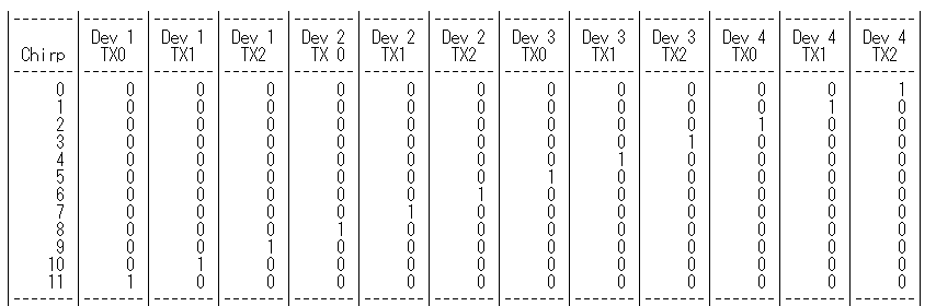
According to the LUA script, the sensor configuration is as below:
------------------------------------------- Sensor Configuration ------------------------------------------------
--[[
The sensor configuration consists of 3 sections:
1) Profile Configuration (common to all 4 AWR devices)
2) Chirp Configuration (unique for each AWR device - mainly because TXs to use are
different for each chirp)
3) Frame Configuration (common to all 4 AWR devices, except for the trigger mode for the master)
Change the values below as needed. --]]
-- Profile configuration
local profile_indx = 0
local start_freq = 77 -- GHz
local slope = 79 -- MHz/us
local idle_time = 5 -- us
local adc_start_time = 6 -- us
local adc_samples = 256 -- Number of samples per chirp
local sample_freq = 8000 -- ksps
local ramp_end_time = 40 -- us
local rx_gain = 48 -- dB
local tx0OutPowerBackoffCode = 0
local tx1OutPowerBackoffCode = 0
local tx2OutPowerBackoffCode = 0
local tx0PhaseShifter = 0
local tx1PhaseShifter = 0
local tx2PhaseShifter = 0
local txStartTimeUSec = 0
local hpfCornerFreq1 = 0 -- 0: 175KHz, 1: 235KHz, 2: 350KHz, 3: 700KHz
local hpfCornerFreq2 = 0 -- 0: 350KHz, 1: 700KHz, 2: 1.4MHz, 3: 2.8MHz
-- Frame configuration
local start_chirp_tx = 0
local end_chirp_tx = 11
local nchirp_loops = 64 -- Number of chirps per frame
local nframes_master = 10 -- Number of Frames for Master
local nframes_slave = 10 -- Number of Frames for Slaves
local Inter_Frame_Interval = 100 -- ms
local trigger_delay = 0 -- us
local trig_list = {1,2,2,2} -- 1: Software trigger, 2: Hardware trigger
--[[
Function to configure the chirps specific to a device
12 chirps are configured below, individually for each AWR device
--]]
-- Note: The syntax for this API is:
-- ar1.ChirpConfig_mult(RadarDeviceId, chirpStartIdx, chirpEndIdx, profileId, startFreqVar,
-- freqSlopeVar, idleTimeVar, adcStartTimeVar, tx0Enable, tx1Enable, tx2Enable)
I understood the number of chirp per frame, number of frames for master and number of frames for slave, however, I did not understand the order of chirp (active antenna).
Could you please tell me the frame structure?
Best regards,
Kawaguchi