This thread has been locked.

If you have a related question, please click the "Ask a related question" button in the top right corner. The newly created question will be automatically linked to this question.

TUSS4470: Ultrasound drive requirement calculation

Part Number: TUSS4470
Other Parts Discussed in Thread: OPA462, TDC1011, LMC555

Hi,

Greetings!

Initially, I thought about using the TUSS4470 for driving this piezo transducer, but then looking at the drive frequency, figure that the TUSS4470 might not be a good choice for driving this transducer ?

(If not, what other options do I have ? H bridge MOSFET with dual gate drivers ? But still then, I was unable to find neither the Gate drivers nor the MOSFET's that could reliably drive the transducer at around 2Mhz ?)

Any suggestions, how to drive this one ?

Thanks,

Manu

  • Hi Manu,

    Based on the request it seems like you are looking for a driver that is capable of driving 1.7 Mhz. Do you know what amplitude would be needed here ? Have you had a chance to look into a linear amplifier ? 

    https://www.ti.com/amplifier-circuit/overview.html 

    With an Opamp perhaps you can drive the transducer ? 


  • Hi Arjun,

    Greetings !

    Indeed, I am looking for a 1.7Mhz driver.

    One of the preliminary issues that I am dealing with, is understanding the amplitude requirements to drive the piezo element.

    All I can find is the frequency and the impedance, I am unable to find the drive voltage specification.

    Any idea, what drive voltage and the power requirements for the piezo element in the link ?

    You meant an opamp like the OPA462 that sounds like an interesting thought, but what about current requirements 

    (The OPA462 can do +/-90V only and 30mA (2.7W) alone. ) ?

    Thanks,

    Manu

  • Hello Manu,

      If you are looking into a simpler solution, you might be looking for a timer/oscillator type of IC. You would then be able to change the RC components to fit the resonant frequency of the piezo transducer. You could also use amplifiers to create this oscillator type of circuit.  I could not find a power rating on the listed part, so not too sure about that specification. I looked at other similar devices on their website and they have around Voltage Input: 24/36Vac and Max Power Input: 20 W. If you want a programmable solution, I would check this part: TDC1011.

    Thank you,

    Sima

  • Hi Sima,

    I think, the discrete oscillator/driver would be the option left, I guess.

    The TDC1011 does not "appear" to have the required output power (though frequency range is the same)

    Even google searches did not help much, in narrowing it down, in my searches.

    How I wish the piezo vendors would write proper specifications for their products, rather than customers making guesses ..

    (I could not find any proper voltage rating either, for the piezo element. Maybe there exists a way to derive the voltage

    requirements from some parameter they have listed, but it goes way beyond my comprehension)

    If someone knows, how to find/calculate the voltage requirements, that would be a great help to chime in here.

    Thanks,

    Manu

  • Hello Manu,

      That is true, if we go by the similar part with power rating specified, then TDC1011 seems to not be capable at those voltages. It is best to contact the manufacturer for the voltage/power input. Are you leaning more towards discrete option or are you still looking into using an amplifier as a multivibrator?

    Thank you,
    Sima

  • Hi Sima,

    Technically it does not matter much either way as long as it works, but having lesser components might be a better choice.

    An RF power amplifier came to mind, but wondered whether the RF amplifier complexity is justified, or maybe at 2MHz, an RF amplifier might not be too complex.

    I guess it would have been simple with some high frequency capable MOSFET's and a high frequency Gate driver.

    But most of them, (MOSFET's as well as the drivers themselves) do not seem to be suited for ~ 2Mhz.

    Well, lost in thoughts ATM.

    Thanks,

    Manu

  • Hello Manu,

      It would depend on power at this point. You could use an amplifier with the necessary frequency range, able to handle a capacitive load of 1450pF, and somewhere near the estimated power necessary. I calculated roughly needing a max slew rate of 250V/us (SR=2piF*Vamp) if going by previous Vac listed for a similar part. Using this tool to look for a suitable amplifier, I have filtered it down to these amplifiers. (Check the datasheet for the figure on capacitive load vs slew rate and bandwidth). You could also do a preamplifier for the oscillating signal, then add a power amplifier stage that will drive the piezo transducer. Or you could use timer/oscillator and add the high frequency transistor/mosfet. I believe the last option would be the best way to approach this application. 

    Thank you,

    Sima

  • Hi Sima,

    Yes, The oscillator option would require me to look for a driver and a MOSFET.

    I think that would be simpler and effective than going in for an amplifier.

    Thanks,

    Manu

  • Hi Manu,

    If you are looking for an oscillator option, you can try the LMC555. It can produce a frequency of up to a 3MHz. A frequency of 1.7MHz will probably require some extra tweaking of the RC capacitor and resistor values to see the right output.

  • Hi Katlynne,

    What drive stage would you suggest ?

    (For the higher voltage and current)

    Thanks,

    Manu

  • Hi Manu,

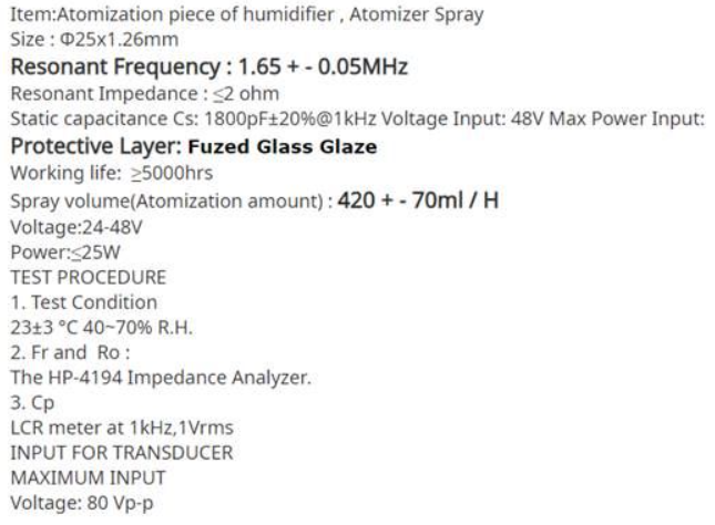
    We think that your part has similar electrical specification as the image captured below (Katylnne found a specification). There are different specifications in the similar part that can be found over the internet. 

    Please verify the following design requirements. Once we are able to finalize the requirements, we can suggest a design approach. We assumed that you want take a low cost approach in the driver design. You may modify the requirements below per your application. The list below is a suggested requirements for now. 

    The device's input voltage: 48Vdc

    Piezo transducer's power: <20W

    Output current is approx. <2Ap-p (sinewave drive) (TBD?)

    Output sinewave in voltage drive at 1.7MHz: TBD? (please verify)

    fr Resonance frequency: 1.7MHz +/-50kHz 

    Operating Temperature: 25C. 40-70%RH

    Atomization amount: approx. 320cc/hr (higher the value, more power you will need for the application).  

    Best,

    Raymond

  • Hi Raymond,

    The resonant impedance what they state is 5 ohms, not 2 ohms.

    But, nevertheless the specs what you state appears to be a good place to start with, I guess ?

    A low cost approach to the driver would be a good design approach; Yes.

    Thanks,

    Manu

  • Hi Manu,

    We would like to know the max. driving amplitudes at 1.7MHz in 25mm RS112 piezo transducer. This is part of TBD from the last reply. It will determine what types of driver that you are going to need. 

    There are multiple driving solutions out there. In the list below, I see multiple inexpensive driving approaches.

    https://www.google.com/search?hl=en&tbm=isch&sxsrf=ALeKk00HB1tXqAyThMkU8uC8x1INgxf8Cg%3A1607093415808&source=hp&biw=1280&bih=579&ei=p0zKX7voLpXb-gTNkILYDQ&q=1.7mhz+ultrasonic+transducer+circuit&oq=&gs_lcp=CgNpbWcQARgAMgcIIxDqAhAnMgcIIxDqAhAnMgcIIxDqAhAnMgcIIxDqAhAnMgcIIxDqAhAnMgcIIxDqAhAnMgcIIxDqAhAnMgcIIxDqAhAnMgcIIxDqAhAnMgcIIxDqAhAnUABYAGCwG2gBcAB4AIABAIgBAJIBAJgBAKoBC2d3cy13aXotaW1nsAEK&sclient=img

    Q: Any suggestions, how to drive this one ?

    If your application is used for mist atomizer or ultrasonic humidifier, the available solutions or circuit are adequate.  The reasons are the resonance frequency has 1.7MHz +/-50kHz range in it. If a circuit is able to drive at the frequency, a required amplitude and current (likely a range of driving amplitude and current),  it will work.  

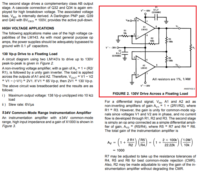
    If your application requires a precision frequency driving at the resonance frequency, and the driving voltage is higher than the supply voltage, you may consider a circuit similar to the one below. Say you want to drive 80Vp-p at 1.7MHz, the following circuit may work (no exactly the same op amps. presented as a floating voltage in piezo transducer driving example). There are other solutions as well, then we may or may not be talking about low cost approach.  

    So the inexpensive approach is to use LC tank circuit to generate 1.7MHz frequency. Alternatively, you can purchase one of driving circuit over the internet, and experiment is a bit and determine the optimum driving specification. RS112 piezo transducer's datasheet is not very specific in the maximum driving amplitude and power requirements. 

    If you are able to provide us the design requirements, may be we are able to narrow down design options. Please let us know. 

    Best,

    Raymond

  • Hi Raymond,

    I have requested the vendor for the detail regarding the drive voltage. Waiting to hear from them.

    Avoiding the amplifier approach, would be the best due to a variety of reasons.

    Driving a piezo element that requires higher currents, with a resonant circuit, I doubt that works ?

    I do agree with you, that the drive voltage data is missing. I wondered about that aspect as well,

    wondered what to do about it, wrote to the vendor too.

    Another thought, I was having: How feasible would it be to drive the piezo element with a MOSFET

    (other than an RF power mosfet, at 2MHz) ?

    Any thoughts ?

    Thanks,

    Manu

  • Hi Manu,

    Yes, the power amplifier approach is a precision design approach, but it is higher cost method and it may not warrant for the applications. We do have power amplifiers that can drive this part.

    General op amp is low cost. You may use general op amp to drive complementary transistor pair to make a high voltage and current driving circuit, which is a low cost approach. 

    Another thought, I was having: How feasible would it be to drive the piezo element with a MOSFET (other than an RF power mosfet, at 2MHz) ?

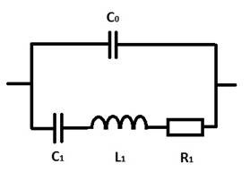
    The regular power MOSFET used in switching power supply should work (IRF44N or similar may work). Make sure that you select low Gate to source capacitance type. You do not need RF power MOSFET. Check out the simulation with selected components. You can back calculated the L and C of the transducer based on the datasheet --> fr = 1/(2*pi*sqrt(LC)). 

    If you have other questions, please let us know. 

    Best,

    Raymond

  • Hi Raymond,


    I'm having a very similar problem. But the cost is not the main concern for me. 

    The specs for the piezo at 2MHz are:

    C0 = (347 +/- 150)pF

    R1 = (1,6 +/- 0,3)Ω

    L1 = (86 +/- 45)µH

    C1 = (69+/- 33)pF

    I would need to realize a precise driver (maybe MOSFET?) with at least 100Vpp, preferably more, and at least 1-2 A.

    Do you have a suggestion for a good combination of gate drivers and MOSFETs for that purpose or maybe another approach?

    Best regards,

    Stefan

  • Hi Stefan,

    Q: Do you have a suggestion for a good combination of gate drivers and MOSFETs for that purpose or maybe another approach? I would need to realize a precise driver (maybe MOSFET?)

    To drive ultrasonic transducer precisely at 2MHz, you will need accurate frequency source. LC tank circuit is not going to be accurate enough for your application. Two methods that you may use to drive the application. 

    1. Use two power amplifiers to drive in opposite phases, each amplifier swings at approx. 50Vp-p with overall voltage amplitude at approx. 100Vp-p. The ultrasonic transducer load will be configured as "float" as shown in LM143, Figure 2 from the prior reply. Of course, we can not use LM143 to drive the application. We need to select PA that is cable to have the BW and current capability for the application. 

    2. Alternative, you may use a power amplifier or amplifier + MOSFET to drive the ultrasonic transducer at 2MHz.  If you want to use N-Mosfet to drive it, you may need BSC900N20NS, BSZ900N20NS3, IRFH5220 or similar power mosfets to drive it. 

    You are unable to drive the ultrasonic transducer with transformer because of the frequency (magnetic core loss will be too high). You have to have current limiting circuit to drive the part as well. 

    If you have other questions, please let me know. 

    Best,

    Raymond 

  • Hi Raymond,

    first of all, thank you for your comprehensive and quick reply!

    As a frequency source, I thought of using an MCU controlled DDS-IC (Direct Digital Synthesis). 

    Approach 2 sounds more interesting to me. How critical are the high capacitance and really low impedance when in resonance at 2 MHz of the PZT? What are the critical specs to look for in a MOSFET for this purpose?
    Would you propose a linear approach like an AB push-pull configuration or a digital half or full bridge approach for this purpose? What gate driver/MOSFET combination would you propose for this application?

    Best regards,

    Stefan

  • Hi Stefan,

    How critical are the high capacitance and really low impedance when in resonance at 2 MHz of the PZT? What are the critical specs to look for in a MOSFET for this purpose?

    If you drive PZT with N-MOSFET, please make sure that Vds is rated at least 2X or higher than the max. driving voltage swings. The gate to source capacitance needs to be low (10nC or lower) range and Rdon resistance needs to be low (heat dissipation will be RI^2). Check the datasheet, if there is gain figures vs. frequency. 

    If you go to mouser.com or digikey.com, you can look up some RF mosfets, which they have much frequency response figures in the datasheet. General power Mosfets do not specify the level of details as RF mosfets do, but you can compare certain capacitive specifications side by side. The questions are amount of losses when switching at 2MHz. I am not sure how well the general PSpice model is able to simulate at the frequency. Generally, any high speed (say above 500kHz) power mosfets used in switching power supply application should work up to 2MHz.  As soon as a part is specified as RF Mosfets, the unit price is up 10X or greater. 

    Would you propose a linear approach like an AB push-pull configuration or a digital half or full bridge approach for this purpose? What gate driver/MOSFET combination would you propose for this application?

    You can use AB push-pull or half or full H bridge to handle the drive. The power mosfet selections are identical to the method above. Generally, we do not work with PZT application as high as 2MHz in discrete components. I have been using our power amplifier to drive the PZT transducer and typically in hundreds kHz range. Many of our power amplifiers have the BW and current capability to drive the load, but I have not simulate the application at 2MHz level. It should be doable, but I do not know what issues that I may encounter.  

    Typically we drive PZT in sinewave, but I read somewhere that it can be driven in square wave as well. Maybe this is something you may consider for your application. 

    If you have other questions, please let us know. 

    Best,

    Raymond