This thread has been locked.

If you have a related question, please click the "Ask a related question" button in the top right corner. The newly created question will be automatically linked to this question.

LMP91000: Warm-up time from standby to temperature measurement

Part Number: LMP91000

Hello everyone,

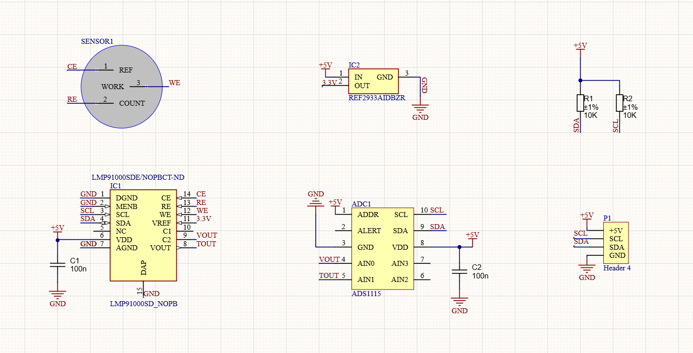
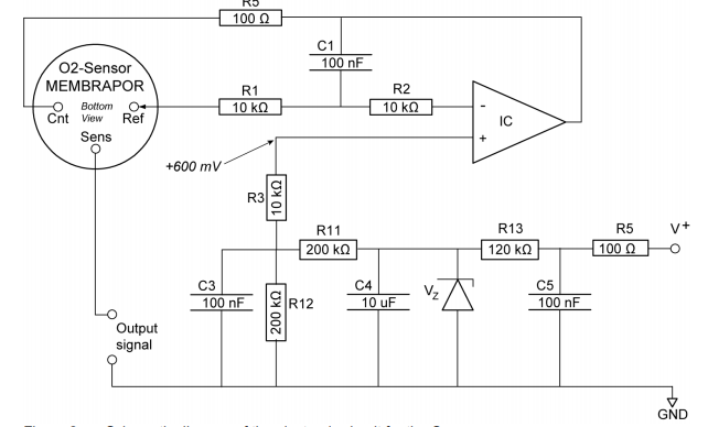
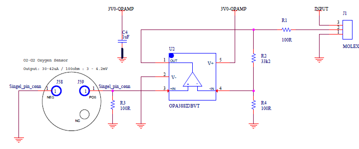
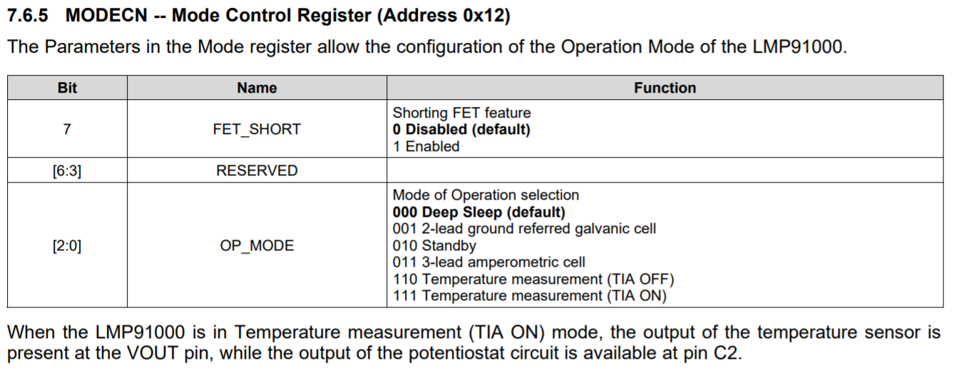
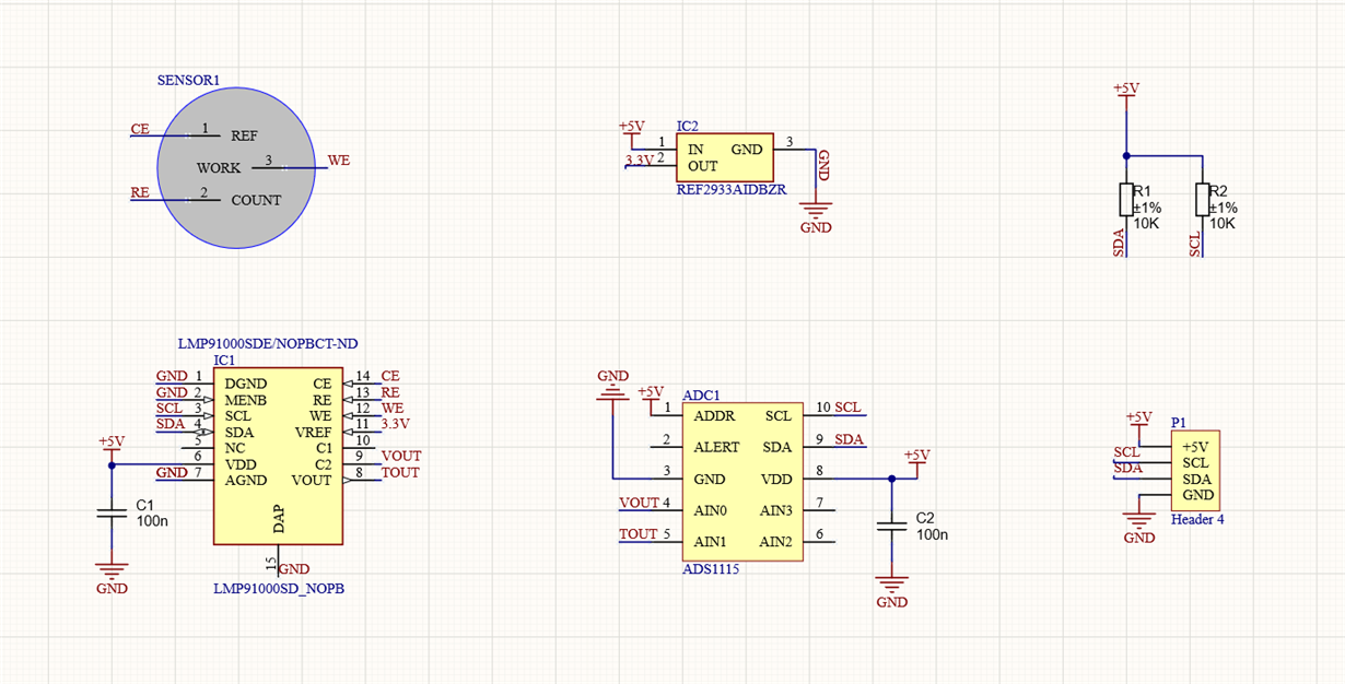
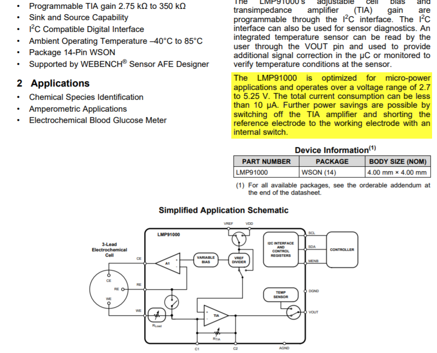
I am using the LMP91000 for oxygen measurement and we need to use the standby mode for lower power consumption, this mode gives us the opportunity to keep the sensor biased when other parts of the IC are off. My problem comes when we switch from standby mode to temperature measurement mode (tia on). We were hoping to have immediate correct values ​​from our sensor. However, we have seen that the sensor takes some time to warm up properly.

After applying standby for 30 seconds, the sensor needs another 30 seconds to give the correct output value, which is meaningless if bias has been applied during standby. Is this performance usual or not?

  • Dear Asier - 

    According to multiple sources on the web, it could take 30 to 60 seconds for O2 sensor to "warm-up" from power applied. I would recommend that you contact the sensor manufacturer to ask about the exact sensor you are using. The LMP91000 does have the standby mode you reference, and if you are using that, please ensure you are not turning off the control amp (A1) at the same time you are turning off the TIA (thus actually removing the bias you think might be there)

  • Hi Josh, 

    Thanks for your reply. I have seen that when standby mode is activated the bias begins to fall, which could mean that the control amp A1 is off. However, this makes no sense because standby doesn't turn off the A1.

    Datasheet: "In the standby mode, the TIA is OFF, while the A1 control amplifier is ON. This mode of operation is suggested when the gas detector is not used for short amount of time and a faster warm-up of the gas detector is required".

    Best regards,

    Asier.

  • Asier - 

    How do you have this wired up? Can you share your connection diagram/schematic? 

  • Hi Josh,

    Here it is.

  • Asier - 

    thanks!

    I see you have CE and RE swapped on the names of the nets of the sensor and also, assuming you mean to use this sensor in potentiostat config, you need to short those same two pins together. See figure 26 on page 19    https://www.ti.com/lit/ds/symlink/lmp91000.pdf

  • Josh

    The names are swapped but they are well connected in my circuit so that is not the problem. On the other hand, my sensor needs a 3 lead configuration since it is an electrochemical oxygen sensor (not galvanic). Info about my sensor: http://file.yizimg.com/3381/2019225-144213788.pdf

  • Asier - 

    Please see here, where they describe using this sensor in potentiostat mode. I think you do need to connect RE and CE together and you can check with the sensor mfg. to make sure. 

    http://www.membrapor.ch/sheet/Application_Note_MEM2_Oxygen_Sensor.pdf 

    In our database of 13 O2 sensors (located in the LMP91000 GUI), every one of them is connected in the manner I pointed you to in the datasheet (on page 19), not page 18 (which shows the galvanic connection)

  • Hi Josh,

    I have read the PDF you attached. They explain pretty well how the circuit works but I don't see the RE connected to the CE, they are using a 3 lead mode.

    However, if you recommend connecting them I will try it.

    Best regards,

    Asier.


  • Asier - that circuit is what you would use if you were not using the LMP91000...

  • I will recommend looking at another sensor

    We had a similar issue with sensors that need constant biasing. That was not possible in our design.

    So we changed to an Alphasense oxygen senor which just requires an external resistor to keep itself biased.. Then you just measure voltage over the resistor. Maybe you can continue to use the TI LMP9100 or a very good low bias Op amp.

  • Thanks for your contributtion Niels,

    Did you also use the same sensor I do? (S+4OXLF).  Reading the datasheet seems obvious that constant biasing is an option using the standby mode, since the control amplifier is always on keeping the sensor biased. Nevertheless, as I've told before the reality is different by the moment.

  • In our design we needed a sensor that could be decoupled completely from any power source and then be ready to run, once the amp was powered up. 

    That is why we selected the Alphasense O2-G2 low profile sensor. It is self biasing when a resistor is connected. And the connector need to be continously connected otherwise the time needed to reach stability are hours.

    R3 is the biasing resistor.


  • If you don't mind attach the picture correctly so I can see it please.

  • Hi Josh,

    I've connected RE and CE. However, the "warm-up" time before the standby mode, continues to be the same. I've measured the voltage betwen WE and CE-RE. It is maintained constant during the Temperature measurement (TIA on) mode. However, when standby mode is activated this voltage begins to fall until Temperature measurement mode turns on again.

    I would say this is owing to the control amp A1 turns off during the standby mode, which should not happen following the datasheet you provide.

    Best regards,

    Asier.

  • Asier,

      Looking at this schematic, What does not make sense to me is that R3 is pulling to ground. You don't have a bias voltage applied to the sensor. Unless you have more for this circuit that is not shown, it is not possible.

    I will review your post and see if I can help you with this issue. More coming soon. 

  • Asier,

      There are 6 functional modes. below is a description of each mode. In the data sheet there is a current breakdown for each mode. Only in the 3-lead amperometric cell mode is everything powered on to be able to make quick measurements.  It clearly states that Standby mode will reduce power consumption, but keep some parts active to reduce startup, but not eliminate startup warm up completely.

    Make sure you select the proper mode for your application. If you need faster start up then you need to be in the 3-lead amperometric cell mode.

    7.4 Device Functional Modes

    The LMP91000 has 6 operational modes to optimize the current consumption and meet the needs of the
    applications. It is possible to select the operational mode through the I2C bus.

    At the power on the LMP91000 is in deep sleep mode. In this mode the device accepts I2C commands and
    burns the lowest supply current. In this mode the TIA, the A1 control amplifier and the temperature sensor are
    OFF. This mode of operation is suggested when the gas detector is not used and a zero bias is required
    between WE and RE electrodes of the gas sensor. The zero bias between the WE and RE electrodes is kept by
    enabling the internal FET feature.

    In the standby mode, the TIA is OFF, while the A1 control amplifier is ON. This mode of operation is suggested
    when the gas detector is not used for short amount of time and a faster warm-up of the gas detector is required.

    In the 3-lead amperometric cell, the LMP91000 is configured as a standard potentiostat with A1, TIA and bias
    circuitry completely ON.

    In the Temperature measurement (TIA OFF) the LMP91000 is in Standby mode with the Temperature sensor
    ON, at the VOUT pin of the LMP91000 it s possible to read the temperature sensor's output.

    In the Temperature measurement (TIA ON) the LMP91000 is 3-lead amperometric cell mode with the
    Temperature sensor ON, at the VOUT pin of the LMP91000 it s possible to read the temperature sensor's output.

    In 2-lead ground referred galvanic cell the A1 control amplifier is OFF and the Internal zero circuitry is bypassed.

    In this mode it is possible to connect 2-lead sensors like the O2 sensor to the LMP91000.

  • Hi Gordon,

    I think you are talking about the schematic Niels sent. In my schematic, there is not any R3 resistor connected to GND. My sensor is perfectly biased until the standby mode turns on.

    Beste regards,

    Asier.

  • Josh,

    Understandably, the warm-up after the standby mode won´t be instant. According to the datasheet during the standby mode, the control amp A1 is on, so the sensor should be biased. However, measuring the voltage between the RE and WE during the standby the voltage falls continuously which makes no sense.

    Our goal was to reduce energy consumption when we are not measuring the oxygen concentration, that is why the standby mode was an interesting option if it could reduce at the same time the warm up time.

    Best regards,

    Asier.

  • Asier,

      You were correct, I was looking at Neils schematic.


  • Asier,

      That makes total sense. When A1 amp is on your are providing a bias voltage, However when TIA is off, WE will float up and WE = CE. Are you turning on the Shorting FET when you enter Standby mode? This will connect WE to RE and keep the sensor biased while TIA is turned off. 

    On the first page of the data sheet there is a brief explanation.

  • Hi Gordon,

    Enabling de FET during the standby mode did not have any positive consequences. The bias needs more time to get to the -600mV since during the standby mode it turns to 0. Shorting those 2 pins could make sense when no power is applied to hold them at the same potential when not in use.

    Apart from that, I have still doubt about why the bias voltage falls during the standby instead of holding the value.

    Best regards,

    Asier.

  • Asier - 

    I would recommend here at this point to use an O2 sensor from the supported database in the LMP91000EVM GUI with your hardware to verify it works - then either switch to that sensor or work with the sensor vendor to determine the difference between how the known sensor works vs this newer type which you are using, and that we have no experience with or samples of.