This thread has been locked.

If you have a related question, please click the "Ask a related question" button in the top right corner. The newly created question will be automatically linked to this question.

IWR6843: Device configuration through SPI

Part Number: IWR6843
Other Parts Discussed in Thread: AWR1243

Hi,

I'm trying to automate the radar device configuration of IWR6843 through SPI and I'm confused by the conflicting documentations:

From mmWaveStudio I read:

```

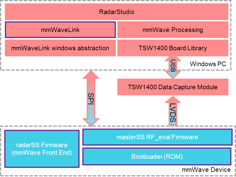
The mmWave device is configured and controlled from the mmWaveStudio by sending
commands to the device over SPI.

```

But from DFP I'm reading

```

The xWR1642, xWR1843 and xWR6843 radar device is configured and controlled using the
internal MCU (Master subsystem) and it communicates with an external ECU using the CAN
interface.
This document only talks about the communication protocol between radar device and external
host processor using SPI in AWR1243. In xWR1642, xWR1843 and xWR6843 the same protocol
is used to communicate between the BIST subsystem and Master subsystem.

```

And in mmwavelink documentation I'm not seeing anything about 6843.

My question is how exactly is mmwaveStudio configuring IWR6843 through SPI and how can I detach the SPI conmmunication from mmwaveStudio and automate it.

Thank you,

PJ

  • Hello

    In order to suggest a good direction to automate  please let us know what is the objective of putting automaton.

    Are you trying to get the Raw Data from device for algorithm development

    or

    Are you trying to develop code post processing of data on the device.

    Regarding your question about what does mmwave studio use for configuring the device. :

    mmwave studio is a utility to capture Raw Data over LVDS interface from TI's mmWave devices. It configures the device over  devices SPI interface.

    To enable this the device is put in Raw data capture mode which provide ability to configure the RF front end of device via SPI interface.  

    In devices which have a host processors integrated  in functional mode configuration of  RF front end is done internally by host processor without the need for SPI interface. Please note this mode of device is different than what mmWave studio uses.

    Thank you,

    Vaibhav

  • Hi Vaibihav,

    Thank you for your reply. My goal is to configure the radar through SPI interface and acquire raw data through LVDS interface (and then through Ethernet over DCA). No data processing is expected on the device integrated processor.

    Regards,

    PJ

  • Hi, PJ:

    Radar studio provide control through MATLAB, and automation through LUA scripts.  Please check radar studio users guide section 22 and section 23. 

    C:\ti\mmwave_studio_02_01_01_00\docs\mmwave_studio_user_guide.pdf

    Other than that, radar studio did not provide any instruction for direct SPI control.

    Best,

    Zigang 

  • Hi Zigang,

    What I'm trying to do is to compile a piece of software based on mmwavelink in order to configure iwr6843 from an external processor, the same way DFP does for AWR1243. It seems to me this is what mmWaveStudio is capable of doing, as I read form the documentation of DFP, v1.2.6.3 page 5 as quoted below. Therefore I wonder if it is possible to remove the interactive interface of radar studio and leave mmwavelink alone in the pipeline. I don't see detailed explanation of the pipeline any where.

    Regards,

    PJ

    "mmWave Studio/Radar studio Tool which is designed to communicate with all variants of TI mmWave devices for RF and system performance evaluation"

  • I wonder if there's anywhere I can find the source code to rf_eval MSS and mmwavelink windows abstraction. Thank you!

  • HI, Pengfei:

    The same mmwavelink is included in the SDK release.  And all the source code of the SDK release is given.  Can you just modify from the SDK OOB demo to achieve your goal?   Instead of SPI, the SDK OOB demo uses UART for configuration, and they also provide raw data transmission option through LVDS. 

    Best,

    Zigang 

  • Hi Zigang,

    If my understand is correct, the sdk demos has data processing units integrated, thus the size of a frame is limited by the RAM size on the chip. We wish to maintain the option of larger frames, thus we found the rf_eval firmware to work for us, and wonder if we can have access to the source code in order to understand how to remove all data processing units.

    Also SPI is a hard requirement for us from the user side.

    Regards,

    PJ

  • HI, PJ:

    Agree with you on the limited frame size, unless you change SDK and remove the post processing chain part.  I will need to consult with the design team and get back to you later. 

    Best,

    Zigang

  • Hi Zigang,

    We were able to get the DFP work with rf_eval images. Still, we are interested if we can read the source code of rf_eval images, or understand how to remove post processing from SDK.

    Regards.

    PJ

  • Hi, PJ:

    I was told that we do not provide the source code of rf_eval images to the public.  Regarding disable post processing from SDK, it is not an easy task.  There is no flag to turn it off, you will have to get familiar with SDK code, and disable the post processing and key memory allocation and initialization.  

    Best,

    Zigang

  • Thank you for your help!