This thread has been locked.

If you have a related question, please click the "Ask a related question" button in the top right corner. The newly created question will be automatically linked to this question.

CCS/AWR1642BOOST: board shuts down at 40 degrees C

Part Number: AWR1642BOOST
Other Parts Discussed in Thread: UNIFLASH, AWR1642,

Tool/software: Code Composer Studio

Help!

i am using the AWR1642BOOST development board and i seem to have hit an issue with temperature instability.

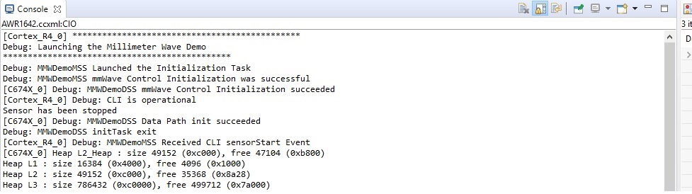
i have programmed the board with the radar data over CAN software and have a working compiling software set in Code Composer studio.

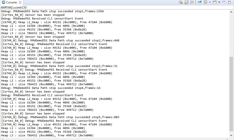
but i seem to have a problem getting the Board to operate at any higher temperature than 40 degrees C. It stops sending CAN Data and freezes until the the power is cycled.

i know there are temperature sensors built into the Radar SOC that are monitored by the RTOS could the problem be here?

  • Hello Dave,

    40c is almost room temperature during hot summer days. That level of temperature shouldn't cause any problem for CAN data communication.

    Silicon can work more than 100c for object detection. Do you face same temperature issue with mmw demo (from mmwave SDK: object data transmit over UART) as well when you run on the board and temperature goes higher.??

    Regards,

    JG

  • Hi Jitendra,

    I reflashed the board to the RADAR Data over UART firmware and with just a COM port client i'm able to maintain communications over the UART over a big temperature range without any lockups.

    i will have to get the visualizer to work (MATLAB runtime issues)  to check properly.

    i forgot to add that i have both the BOOST and the BOOST- ODS version and they both suffer the same problem. so that what tipped me off to it most likely being a software related issue.

  • Just a bit more info, i have now found out that the ARM processor portion of the Radar system is not crashing, it is the either the digital signal processor or the Radar Subsystem not sending any data to be sent out Via CAN.

    When i press the button for switching the radar on and off , on the demo board. The status LED changes state which means the ARM processor is still operating.

    I am using the  mmWave Automotive toolbox Lab 0005 software if anybody can replicate this problem and help me solve this it would be appreciated thanks.

  • Hello Dave,

    Let's check the setup one by one with following steps.

    1. Flash mmw demo from mmWave SDL 3.4 version and post flashing check object data plot with mmWave Demo Visualizer. Follow the mmwave SDK user guide for exact step to flash and run mmw demo with AWR1642BOOST.

    2, If above works fine then go for lab005 in CS debug mode, where you need to first flash ccsdebug.bin file to device then load the *.xer4f and *.x674 image via CCS to the device and then run it. This way you will get log message over CCS console if MSS/DSS raises any error during execution.

    Regards,

    Jitendra

  • Hi Jitendra,

    The mmWAVE demo in the SDK works without any issues, no matter how hot i make it. 

    i have managed to get the debugger setup and have the CAN software running in CCS with the console on and i'm getting all of the start up information in the console.

    The CAN software will still stop when i warm the board up but it doesn't throw any errors in the console when it does. So investigated a little further, when i manually switch the sensor on and off using the button,

    the console will display that the sensor is switching and off  successfully and gives a frame count from the sensor.

    The CAN messages never restart though. 

  • Hello Dave,

    It is strange that with CAN application only you are facing this issue.

    Let's do some experiment to isolate the issue, if it is due to CAN interface or some other reason.

    I hope you are flashing default binary file from this TI-Rex link to the device-

    https://dev.ti.com/tirex/explore/node?node=ADWAvz1GWDvSfSVkncqhEw__AocYeEd__LATEST

    Please confirm if with this binary you are not getting object data on CAN visualizer (visualizer comes with this lab package).

    Now if that doesn't stream object data after sensor is getting hot then 

    1. Flash ccsdebug.bin from mwmave SDK 2.1 (c:\ti\mmwave_sdk_02_01_00_04\packages\ti\utils\ccsdebug) to the device using UniFlash

    2. Boot the device then in functional mode 

    3. Connect CCS to MSS and DSS cores.

    4. load xwr16xx_odoc_ti_design_mss.xer4f and xwr16xx_odoc_ti_design_dss.xe674 iamge to MSS and DSS repectively from lab0005_object_data_over_can\odoc-target\pre-built-Binaries\  path.

    5. Execute MSS then DSS core from CCS.

    6. Connect CAN visualizer to check object result on the visualizer screen (follow MMWAVECANVISUALIZER_UserGuide.pdf)

    7. If after some time visualizer stops plotting object results then--> 

    a. Halt MSS core from CCS and put breakpoint in Get_CanMessageIdentifier function, then execute MSS core

    a.1  if it MSS application hits this breakpoint then it proves that DSS is able to calculate the object result and send result to MSS over mailbox. So problem is somewhere while sending that data over CAN.

    a.2 if it doesn't then trace this back to DSS end:  halt DSS core, check if it is not in some error state/ASSET.  then put breakpoint at MmwDemo_dssSendProcessOutputToMSS function-> if not hitting here then put breakpoint at MmwDemo_processChirp and MmwDemo_interFrameProcessing function, to check if DSP is still able to do chirp/frame processing.

    This way you can trace back the device issue with CAN application.

    We don't see any issue with the default CAN application at our end, so need to understand situation there.

    New Comment::--

    For the CAN communication to work correctly accurate baud rate needs to be set on the CAN receiver side,  can you double check the settings on the receiver match the CAN setting on the Lab005 application? PPM frequency mismatch can cause reception failure. First, you could just probe the CAN TX pin from the AWR device (before the CAN PHY) to check if during the “lockout” the CAN TX o/p from our device also stops or is it just the data reception failure on the CAN receiver side.

    Regards,

    Jitendra

  • hi Jitendra,

    i have gone through the debug process with a break point set on the Get_CanMessageIdentifier function, this function continues to be called even when the CAN messages have stop working.

    i have checked the CAN_TX pin the on the processor with an oscilloscope and there is no CAN traffic appearing on the pin. The CAN peripheral is not sending packets for some reason, why i'm not certain.

    ***further investigation****

    I stepped through the calls and found that in CANFD_transmitData, there is a failed pending message flag check each time it tries to send a packet, this could mean there is some data stuck that's not being sent for some reason.

    baseAddr = ptrCanFdMCB->hwCfg.regBaseAddress;

    /* Check for pending messages */
    index = (uint32_t)1U << ptrCanMsgObj->txElement;
    if (index == (MCAN_getTxBufReqPend(baseAddr) & index))
    {
    *errCode = CANFD_EINUSE;
    retVal = MINUS_ONE;
    }

  • Could you check if device is getting any CAN protocol error?

    gErrStatusInt from MCANAppErrStatusCallback function.

    That's the only hunch I have right now.

    Regards,

    Jitendra

  • Hi Jitendra,

    I put a break point there and it seems that under normal operation we to get a lot of CANFD_Reason_PROTOCAL_ERR_DATA_PHASE errors.

    If i get the processor into the condition where it doesn't send CAN messages anymore. i get no more breaks at the MCANAppErrStatusCallback function.

    I'm not sure what a CANFD_Reason_PROTOCAL_ERR_DATA_PHASE error is.

    *****further investigation*****

    I put a break point in the CANFD_MCANInt0Isr interrupt handler at line 109 in  canfd.c, it is triggered if we are sending CAN messages but stops being triggered if the messages stop.

    so i moved the break point around inside of the interrupt handler and found i am getting a  CANFD_Reason_PROTOCOL_ERR_ARB_PHASE or a to a lesser degree CANFD_Reason_BUSOFF .

    These errors will both cause the interrupt handler to be no longer triggered (maybe due to peripheral shutdown or lockout).

     One of these errors is related to bit timings and the temperature shift causing them would make me suspected which oscillator the CAN was referenced against.

  • Hello Dave,

    Do you another AWR1642 board with you where you can try same experiment? As default CAN TI-Rex application should work fine. At my end I don't see any issue. so just need to see if that specific board is generating this issue.

    Regards,

    Jitendra

  • Hi Jitendra,

    I have a AWR1642BOOST-ODS board.

    it does the same thing, if the board is allowed to get to warm the CAN messages cease. i was using this board originally and hoped the problem would disappear when i swapped to the normal AWR1642BOOST board but the issue remained.

    Kind Regards,

    Dave.

  • Hi Jitendra,

    i have tried it on both my boost and my boost ODS boards with the same result, i have ordered new boost board that should arrive today. I think the next best move if new board doesn't work, is for me to program a board and send it to you so you can see a not working one and hopefully see what can be done to solve the problem.

  • Hello Dave,

    Ideally shipped board has been verified with OOB demo and should work with other interfaces as well.

    Hope with new board it should work at your end.

    Regards,

    Jitendra

  • Hi Jitendra,

    I have tried the new board and it does the same thing, i have included a video of the test.

    i had my colleague warm it up with a hairdryer. 

    you can see it cutout at 40C, i have both the visualizer and the Pcan View open on the screen so you can see the CAN messages stop.

  • This is really unexpected behaviour of device.

    Let me check with hardware team and get back to you by end of this week at high priority.

    Regards,

    Jitendra

  • Hello Dave, 

    We need probe AWR CAN TX output (before the CAN PHY) to see if that is stopping or is the receiver not able to interpret the data. Would it be possible to do that? This way we can confirm if CAN data stopped from AWR device itself not blocked by the PHY.


    Regards,

    Jitendra

     
  • Hi Jitendra,

    Yes the CAN data stops coming out of the AWR SOC device itself , all CAN activity stops on the CAN TX pin of the AWR SOC

    i tried sending some data from the computer back to the AWR board and it appears correctly at the CAN RX pin of the AWR SOC so the CAN PHY seems fine.

  • Hi Dave,

    I have forward this issue to hardware team.

    Please expect reply by Monday.

    Regards,

    Jitendra

  • Hi Jitendra,

    Thanks for trying. Ill await the response of the hardware team, i'm pretty much stuck now until i can get this resolved as its stopping me casing the the board up so i can test in it intended application.

  • Hello Dave,

    Could you provide setting in the PCAN-view?

    Please confirm if you are using mmWaveCANVisualizer.exe from odoc-host\gui\gui_exe directory.

    If the sample point in your PCAN-view setting is less 75% then device generates those CANFD errors. So make sure that you set sample point more than 75 in PCAN view (if you are using PCAN-view not mmwaveCanVisualizer.exe)

    CAN is handshake based protocol, if device CAN interface doesn't get ACK from external CAN host then it polls for sometimes and then stop sending data. So your error may depends on external PCAN dongle as well.

    Regards,

    Jitendra

  • Hi Jitendra,

    All my setting are ok and I'm using the visualiser that from odoc-host, i made my software was up to date as well.

    though the default CAN settings in the visualiser seem to set the data bit sample point to 62.5%

    I have tried playing around with different sample points to see if anything changes and they all seems to end in the same result or do not work at all.

    The other bit of equipment that i have designed to go with this gets the same results as the dongle so i think the dongle is fine.

    Kind Regards,

    Dave Bennett.

  • Hello Dave,

    That is very strange that this kind of issue we haven't heard from any other customer even using EVM or thier custom board.

    Even at my end also, it works without any issue. And I hope you are using TI-CAN-VIsualizer tool for this experiment, not PCAN GUI even with same setting.

    We need to read back the device internal temperature and other debug data. 

    Same application uses UART to send the debug data. Could you edit the same to send device temperature at some period?

    You can use rlRfGetTemperatureReport API to do that, refer C:\ti\mmwave_sdk_03_05_00_01\packages\ti\control\mmwavelink\test\common\link_test.c file for this API implementation.

    And could you dump all the CANFD register memory content into a file from CCS memory browser when this issue happens, we can analyse the CANFD peripheral registers' status.

    Check that there is no ESM or CPU fault happens during this time.

    Regards,

    Jitendra

  • Hi Jitendra,

    I managed to get the temperature readings.

    typedef struct rlRfTempData
    {
        /**
         * @brief  radarSS local Time from device powerup. 1 LSB = 1 ms
         */
        rlUInt32_t time;
        /**
         * @brief  RX0 temperature sensor reading (signed value). 1 LSB = 1 deg C
         */
        rlInt16_t tmpRx0Sens;
        /**
         * @brief  RX1 temperature sensor reading (signed value). 1 LSB = 1 deg C
         */
        rlInt16_t tmpRx1Sens;
        /**
         * @brief  RX2 temperature sensor reading (signed value). 1 LSB = 1 deg C
         */
        rlInt16_t tmpRx2Sens;
        /**
         * @brief  RX3 temperature sensor reading (signed value). 1 LSB = 1 deg C
         */
        rlInt16_t tmpRx3Sens;
        /**
         * @brief  TX0 temperature sensor reading (signed value). 1 LSB = 1 deg C
         */
        rlInt16_t tmpTx0Sens;
        /**
         * @brief  TX1 temperature sensor reading (signed value). 1 LSB = 1 deg C
         */
        rlInt16_t tmpTx1Sens;
        /**
         * @brief  TX2 temperature sensor reading (signed value). 1 LSB = 1 deg C
         */
        rlInt16_t tmpTx2Sens;
        /**
         * @brief  PM temperature sensor reading (signed value). 1 LSB = 1 deg C
         */
        rlInt16_t tmpPmSens;
        /**
         * @brief  Digital temp sensor reading (signed value). 1 LSB = 1 deg C
         */
        rlInt16_t tmpDig0Sens;
        /**
         * @brief  Second digital temp sensor reading (signed value).( applicable only in \n
         *         xWR1642/xWR6843/xWR1843.) \n
         *         1 LSB = 1 deg C \n
         */
        rlInt16_t tmpDig1Sens;
    }rlRfTempData_t;
    
    Temperature readings once a second
    
    RX0,RX1,RX3,RX3,TX0,TX1,TX2,PM,DIG
    
    40,39,45,43,41,43,42,44,44,43
    40,40,46,43,42,43,43,45,45,43
    40,40,46,43,42,43,42,45,45,44
    39,40,46,43,42,43,43,45,45,44
    40,40,46,43,43,43,43,45,45,44
    40,40,46,43,42,43,43,45,45,44
    40,40,46,43,43,43,43,45,45,44
    41,40,46,43,43,43,43,45,46,44
    40,40,46,43,43,43,43,45,46,44
    40,40,46,43,42,43,43,45,46,44
    40,40,46,43,43,43,43,45,45,44
    41,40,46,43,43,43,43,45,46,44
    41,40,46,43,43,44,43,46,45,44
    40,40,46,43,43,44,43,45,46,45
    40,40,46,43,43,44,43,45,46,45
    41,40,46,43,43,43,43,46,45,44
    40,40,46,43,43,43,43,45,46,45
    40,40,46,43,43,44,43,46,46,45
    41,40,46,43,43,44,43,46,46,45
    40,40,46,43,43,44,43,46,46,45
    40,41,46,43,43,44,43,46,46,44
    40,40,46,43,43,44,43,45,46,45
    40,41,46,43,43,44,43,46,46,45
    41,40,46,43,43,44,43,46,46,45
    41,41,46,43,43,44,43,46,46,45
    41,41,46,43,43,44,43,46,45,44
    41,40,46,43,43,44,43,46,46,45
    40,41,46,43,43,44,43,46,46,45
    41,40,46,43,43,44,43,45,46,45
    41,40,46,43,43,44,43,45,46,45
    41,41,46,43,43,43,43,46,46,45
    41,41,46,43,43,44,43,46,46,45
    41,41,46,43,43,44,43,46,46,45
    41,40,46,43,43,44,43,46,46,44
    41,40,46,43,43,44,43,46,46,45
    41,40,46,43,43,44,43,46,46,45
    41,41,46,43,43,44,43,45,46,45
    41,41,46,43,43,44,43,46,46,44
    42,40,46,44,43,44,43,46,46,45
    41,41,46,43,43,44,43,46,46,45
    41,41,46,43,43,44,43,46,46,45
    41,40,46,43,43,44,43,46,46,45
    41,41,46,43,43,44,43,46,46,45
    41,40,46,43,43,44,43,46,46,45
    41,41,46,44,43,44,43,46,46,45
    41,41,46,43,43,44,43,46,46,45
    41,41,46,43,43,44,43,46,46,45
    41,40,46,43,43,44,43,46,46,45
    41,41,46,43,43,44,43,46,46,45
    41,41,46,43,43,44,43,46,46,45
    41,41,46,43,43,44,43,46,46,45
    41,41,46,43,43,44,43,46,46,45
    41,41,46,43,43,44,43,45,46,45
    40,41,46,43,43,44,43,45,46,44
    40,40,46,43,43,44,43,46,46,45
    41,41,46,43,43,44,43,46,46,45
    41,40,46,43,43,44,43,46,46,45
    41,40,46,43,43,44,43,46,46,45
    41,41,46,43,43,44,43,46,46,45
    40,41,46,43,43,44,43,46,46,45
    41,41,46,43,43,44,43,46,46,45
    41,41,46,43,43,44,43,46,46,45
    41,41,46,43,43,44,43,46,46,45
    41,41,46,43,43,44,43,46,46,45
    41,40,46,43,43,44,43,46,46,45
    41,41,46,43,43,44,43,46,46,45
    42,40,46,44,43,44,43,46,46,45
    41,40,46,44,43,44,43,46,46,45
    41,41,46,44,43,44,43,46,46,46
    41,41,46,43,43,44,43,46,46,45
    41,41,46,44,43,44,43,46,46,45
    41,40,46,43,43,44,43,46,46,45
    41,41,46,43,43,44,43,46,46,45
    41,41,46,43,43,44,43,46,46,45
    41,41,46,44,44,45,44,46,46,46
    43,43,48,46,46,47,46,48,48,47
    46,45,51,49,49,49,48,50,51,50		- CAN ceases to function here
    48,48,53,51,51,52,51,53,53,52
    47,47,52,50,49,50,50,52,52,51
    46,47,52,50,49,50,49,52,52,51
    47,46,52,49,49,50,49,51,52,50
    46,46,52,49,49,50,49,51,52,50
    47,46,52,49,49,49,49,51,51,50
    46,46,52,49,49,50,49,51,51,50
    46,46,52,49,49,49,48,51,51,50
    46,46,51,49,48,49,48,50,51,49
    47,46,51,49,48,49,48,50,51,50
    46,45,51,49,48,49,48,50,51,49
    46,45,51,49,48,49,48,50,50,49
    46,46,51,49,47,49,48,50,50,49
    46,46,51,49,48,49,47,50,50,49
    46,45,51,48,48,49,48,50,50,49
    45,45,51,48,47,49,47,50,50,49
    45,45,51,48,47,49,47,50,50,49
    45,44,51,48,47,48,47,49,50,49
    45,45,50,48,47,48,47,49,49,49
    45,45,50,48,47,49,46,49,49,49
    44,44,50,48,47,48,47,49,50,49
    45,44,50,47,47,48,47,49,49,49
    44,45,50,47,46,48,46,49,49,49
    45,44,50,47,47,48,47,49,50,49
    

    and here are the before and after memory dumps

    before.dat

    after.dat

    I also experiemented  a bit and found this out.

    When the CAN cuts out its because Bit 0 of the MCAN_CCCR register is set. if i clear the bit on errors it starts working again but throws ESI errors until the chip cools down again and at that point it works as normal again.

    Reading the Reference manual it says that Bit 0 can bit set by a message memory uncorrected bit error or by going into a Bus off state.

    I did check the Message memory (0xFF500408) but i didn't find anything obviously wrong but i don't know if the memory has been overwritten before an error is thrown.

    Kind Regards,

    Dave Bennett.

  • Hi Jitendra,

    Another update on what i'm trying so far, i have edited the software so it only sends a fixed test packet over CAN. i commented out where it sends The radar data.

    I did my usual temperature test and the CAN carried on working with no errors, so that now narrows it down to Bad data ending up in the CAN transmit buffer some how.

    i'm going to use a process of elimination on the CAN packets to see if its any particular one that's causing the issue.

  • Hello Dave,

    This latest debug info is very helpful to check it further.

    1) I haven't got confirmation from you over the past conversation that you are observing this issue with default CAN application (from TI-Rex).

    https://dev.ti.com/tirex/explore/node?node=ADWAvz1GWDvSfSVkncqhEw__AocYeEd__LATEST

    Could you confirm if you are seeing this error with default binary image?

     2) Make sure that you have connected Ground pin on PEAK dongle to EVM CAN connector.

    Regards,

    Jitendra

  • Hi Jitendra,

    Yes i'm using the standard default software, initially i was literally just up loading the pre-compiled binary file in "lab0005_object_data_over_can" into the demo board when the problem came apparent.

  • Hello Dave,

    As per your last reply, it was working fine when you use fixed data instead of object data to send over the CAN. 

    As object data generated can be of different size at every frame and it can be big size as well.

    Could you try to generate same size of fixed data which you need to send at every frame similar to object data streaming over the CAN?

    This way we can prove that when data is of huge size and are back to back many chunk then over the time/temperature CAN interface get stuck.

    And could you change bit timing values so that the sample point is higher than 75% at the PEAK GUI or visualizer setting?

    Regards,

    Jitendra

  • Hi Jitendra,

    i have had some success, a combination of setting the sample point in the Visualiser to 85% and adding some code into the error handler to reset the CAN peripheral seems have gotten me something i can work with on the demonstration board, i still get the an error once in a blue moon but it now can not lock the system up and it recovers.

    Hopefully i will be able to get it working on the prototype PCB's that are now ready,

    Thanks for your time and Patience,

    Dave Bennett.