This thread has been locked.

If you have a related question, please click the "Ask a related question" button in the top right corner. The newly created question will be automatically linked to this question.

DRV5032: The output toggle issue

Part Number: DRV5032
Other Parts Discussed in Thread: TMAG5123EVM

Hi Bu,

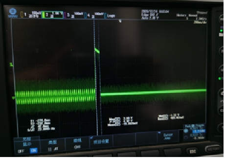
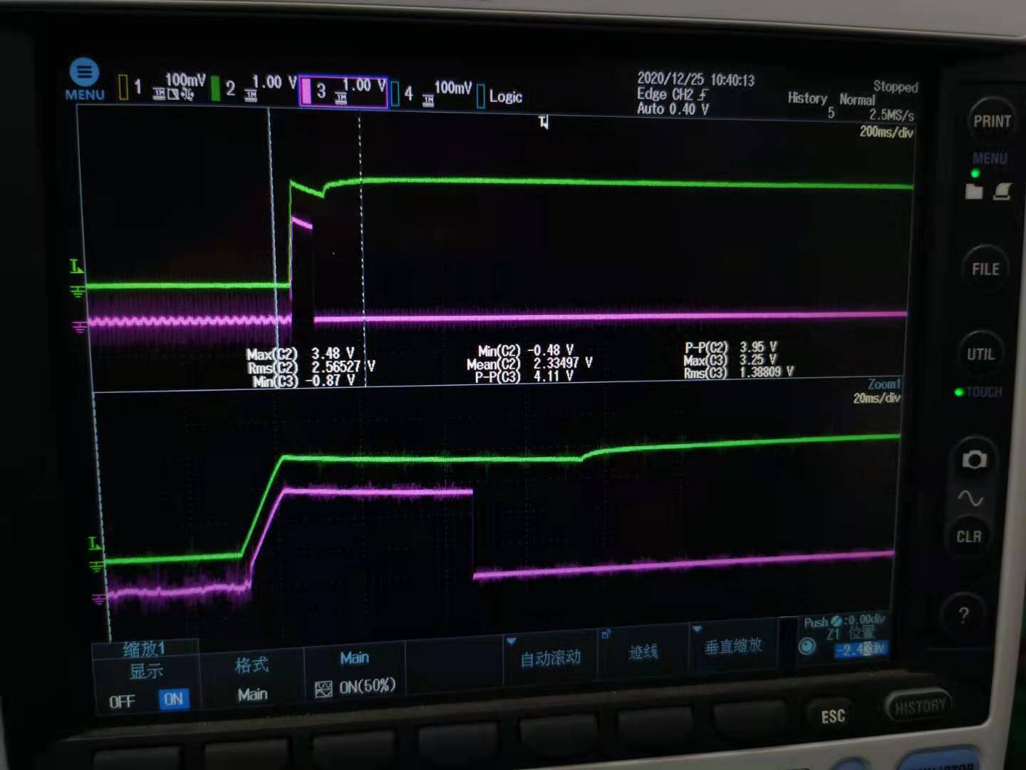
I have a question regarding DRV5032FA , when power on the device by 3.3V, there will be a toggle(3.3v, duration is 200mS) on the output which is not I expect.

Could you please tell me if this phenomenon is reasonable , how can I eliminate the toggle?

  • One more information: 

    If move the magnet closer to the hall and power on this device, there is no toggle issue , output is keeping the low level.

    If move the magnet a little bit far away from the hall than the above position, there is the toggle issue.

  • Hi Jason, 

    Our experts on this device have been notified of this question, but are out for the winter holiday. Please allow up to a week for their response. 

    For now I would suggest:

    - make sure the power supply recommendations and layout guidelines are followed

    - provide a scope plot capture of VCC and OUT from start up until OUT is stable, for both cases. 

    Regards,

    Gabriel

  • Jason,

    Thank you for reaching out.  The normal startup time for DRV5032 has a maximum of 100 usec.  I would expect to have seen the output settled to the expected value within this time frame.

    Can you provide another scope capture with better resolution showing Vcc and Out? Please zoom in more closely on the region surrounding the pulse.

    Is there any other external circuitry beyond what is depicted in figure 22 of the datasheet, such as an RC filter on the output, or pull-up resistor?

    Thank you,

    Scott Bryson

  • Hi Scott:

    Thanks for your reply.

    There is a RC filter on the output of DRV5032 (1KOHM + 1.5nF) , no additional load .

    Please check the below waveform which the Vout in align with the VCC.

    One thing i need to mention here is that period of the high level will be restored to the 50uS if place the magnet closer to the hall (the distance from 4.2mm to 3.8mm), so this issue might be related to the distance between the hall and the magnet.


  • Jason,

    Can you describe the magnet position related to normal operation in your system?  Is this just at the normal trip point?  You indicated that moving the magnet closer results with the device starting up within 50 usec in the low output state, correct?  Can you confirm that you see the device startup and remain high when you move the magnet further away from the sensor?

    Can you provide magnet dimensions and material so that we can determine the magnetic flux density at your startup location?

    Thanks,

    Scott

  • Jason,

    I am checking in again to see if you are able to confirm the output remains high when you power on with the magnet further from the sensor.

    Additionally, I would suggest attempting the startup routine with the RC circuit on the output removed to verify this is not impacting the result.

    Thanks,

    Scott

  • Hi  Scott:

    Sorry for my late response since we have found a workaround ( more closer to the hall ) to fix it.

    So, for the project schedule , we didn't do further test to deep dive this issue . However , i think we need to figure out the reason why the long term high level on the output during the power on.

    If the magnet further from the sensor , the period of the high level on the output during the power on will be longer , like several dozens of mS, If closer to the sensor,the period is shorter as well as the attitude. 

    I have no EVM by hands, could you please check the issue in your lab ?

    i will ask customer to remove the RC filter in their design if they have time. 

  • Jason,

    I have a TMAG5123EVM which allows for testing any 3 pin SOT-23 Hall Effect Sensor.  I used a DRV5032FA device and slid a magnet I had available on the track up to the point where the output toggles and then I fixed it in place. I can then repeatedly apply and remove power to the PCB while monitoring the output.  At power on I see the normal behavior with a short duration pulse that is well within the 100 usec maximum Power-On time.

    If I move the magnet slightly further away, then the sensor keeps the output high.

    I have made several attempts right around this point, and have so far been unable to reproduce the reported behavior of a long startup pulse.

    In addition to verifying whether the RC filter is impacting the startup, please ask the customer to ensure that the system is stable and that the magnet system is not mechanically disturbed during the test.  If the magnet is placed perfectly at the threshold point for the sensor, it is possible that a slight bump could impact the gap enough to cause a temporary delay in activating the threshold.

    Thanks,

    Scott