This thread has been locked.

If you have a related question, please click the "Ask a related question" button in the top right corner. The newly created question will be automatically linked to this question.

IWR6843: Regarding flash procedure using USB to TTL Converter

Part Number: IWR6843
Other Parts Discussed in Thread: UNIFLASH, , MMWAVEICBOOST

Hi Team,

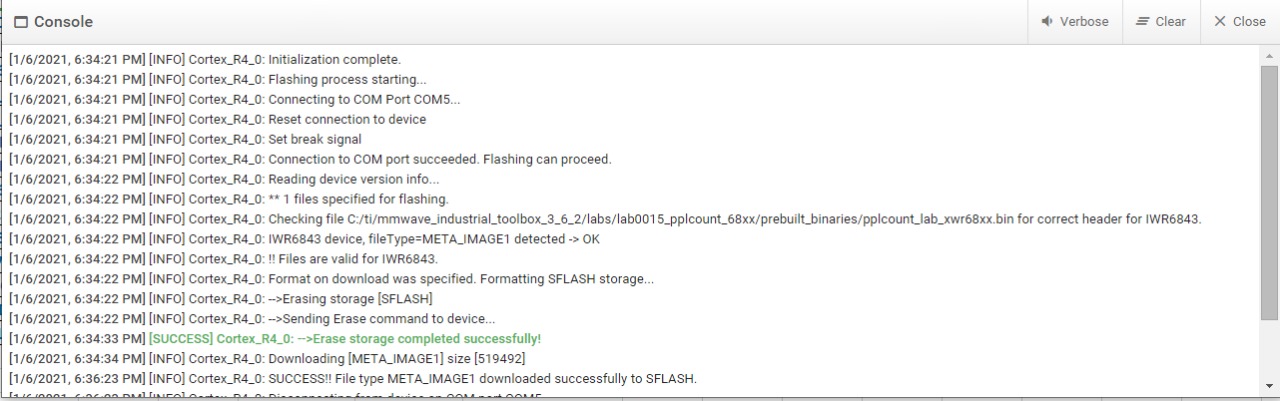
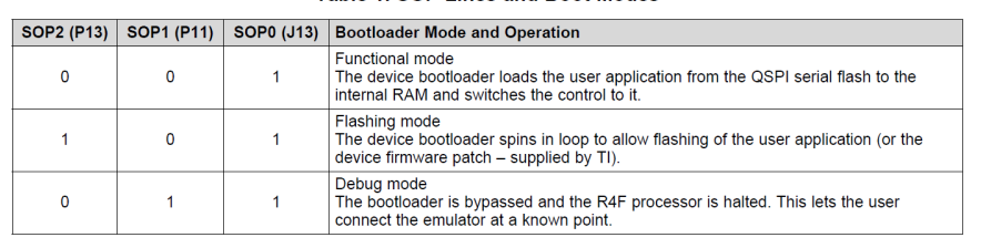
This message is regarding the flashing procedure. i have a USB to TTL converter and IWR6843 sensor with a know pin number. I have connected SOP pins from the IWR6843 sensor to GND and 3V3. I am trying to flash the bin file using the UniFlash tool, but I am unable to proceed further. I am getting an error called "[ERROR] Cortex_R4_0: Serial port COM11 specified does not exist, is already open, or permission is denied!!". my question here is I am doing procedure current or wrong. If the wrong is there any alternative procedure to identify SOP pins and flashing procedure. the below screenshot is for your reference (flash mode and functional mode).

Regards,

Srikanth

  • Hi Srikanth

    You will need to provide more information on the protocol you are using for UART conversion. Can you post a screenshot?

    Please note UNIFLASH is the only supported method for flashing mmWave Devices. Are you able to flash the device using UNIFLASH normally?

    Regards,

    AG

  • Hi Akash,

    Thank you for the update.

    I am using RS232 Rx/Tx pins from the IWR6843 sensor. trying to flash the mmwave sensor using UniFlash but, I am unable to flash it.

    Regards,

    Srikanth

  • can you please reply to my query.

    SOP[0, 1, 2] pins are required to connect the IWR6843 sensor. SOP[1] is connected to GND and SOP[1, 2] pins are No Connection(NC), RS232 Rx/Tx pins are used, and trying to flash bin file using UniFlash but in the console log, I am getting below data. here I have attached a screenshot for your reference. please help me with this. if any pin is required to connect IWR6843 to flash the bin file.

    Regards,

    Srikanth

  • Hi Team,

    I am eagerly awaiting your response. can you give me a reply to the above query.

    Regards,

    Srikanth

  • Hi Srikanth

    Please see the schematic for MMWAVEICBOOST on page 14 the SOP connections are listed. You'll want to connect SOP 0 and SOP 2 for flashing mode and be able to disconnect SOP 2 for device usage thereafter. Is this part clear? 

    Your previous post says SOP 1 is connected to GND while SOP 1,2 are not connected, can you clarify?

    Regards,

    AG

  • Thanks for the update  Akash.

    I meant to say, In flashing mode SOP[1] is connected to GND, and SOP[0,1] is No Connection(NC). it means Open. is my observation is correct or wrong?

    I have few questions. can you clarify below mwntioned points.

    1. Setup Board -1 (Includes Debugger with IWR6843 RF sensor)

    • I took 1 debugger board and 1 IWR6843 sensor.
    • Power on the Debugger using a 12V/1.5A power supply.
    • Plug in micro-usb and power supply to EVM using the connector
    • I have opened UniFlash tool, select the com port and bin file located in local drive.
    • In console window i have observed set break signal, i pressed the push button and release it. isthere any importent role for set break signal.
    • after release button, i am successfully able to flash the bin file into IWR6843.

    For your reference here i am attaching console window output.

    2. Setup Board -2 (Includes Custom board and IWR6843 RF Sensor)

    • I have followed same steps above mentioned question 1. but i was not able to flash the bin file into IWR6843 sensor.
    • I have strcuked read information from device. for your reference i have attached console window output screenshot. 

    3. Timing Diagram.

    • As per IWR6843 datasheet, i have checked timing diagram, I observed SOP[2, 1, 0] , nRESET and WARMRST is paying any role to swiched to flash mode to functional mode. or other then this 3 pins any pins requred to enter into the flash mode.
    • NERROR_IN and NRST pins are playing any import role. or any hand shaking is requred to wake up device and start the Flashing mode.
    • Here I have attached timing diagram for your reference.

    Please do the needful. your answers are very importent to execute my project.

    Regards,

    Srikanth

  • Thanks Srikanth

    Thanks for the info and clarification. I've asked a hardware expert to look into your query, we should have an answer for you by the end of the week.

    Regards,

    AG

  • Srikanth Katakam1 said:
    I meant to say, In flashing mode SOP[1] is connected to GND, and SOP[0,1] is No Connection(NC). it means Open. is my observation is correct or wrong?

    For flashing mode SOP[1] should connected to GND and nd SOP[0,1] should be pulled up not NC.

    Can you make this adjustment and confirm if you are able to flash now?

    Also not every USB to UART converter is supported on uniflash, if possible can you program an known working board using the USB to UART?

    Regards,

    Charles O

  • Yes, I was able to flash the bin file into IWR6843.

    Thanks for the update Charles.

    Regards,

    Srikanth

  • For Function mode, how to set the SOP pins can you elaborate as you explained in the previous message for flash mode. other than these SOP pins is there any pin is required to set the function mode. please do the needful.

    Regards,

    Srikanth

  • Hi Team,

    I'm eagerly awaiting your reply, please respond to the previous message.

    Regards,

    Srikanth

  • Hello

    Are you using TI's IWR6843 based EVM ?

    Or

    Is this custom designed Hardware?

    Thank you,

    Vaibhav

  • Hello,

    Yes, this is custom-designed hardware (IWR6843 QG + ESP32 MCU).

    Regards,

    Srikanth

  • Hello

    Would you be able to provide  the timing diagram for   SOP pins, Power supply rails, reset and clock pins of the device

    and confirm if these match the datasheet waves provided in the device Datasheet.

    Thank you,

    Vaibhav