A related question is a question created from another question. When the related question is created, it will be automatically linked to the original question.
If you have a related question, please click the "Ask a related question" button in the top right corner. The newly created question will be automatically linked to this question.
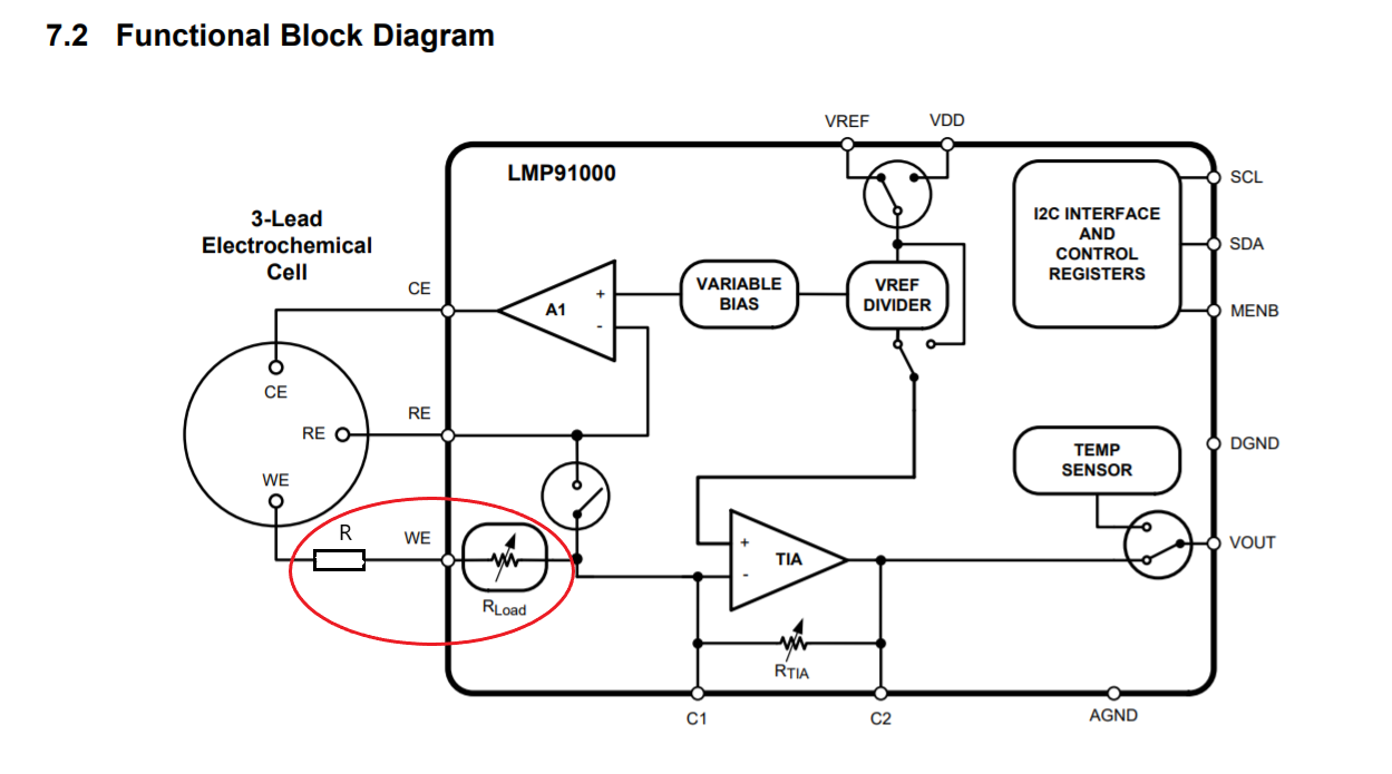
Because the sensor needs 200 Ω resistance, and the Rload of LMP91000 can be configured with a maximum of 100 Ω, I'd like to know whether a resistor can be connected in series at the WE end of LMP91000
According to the data sheet it is possible to add the external resistance. However the extra resistance will change the current and potentially the CE voltage. It will also effect the gain of the transimpedance amplifier. (see data sheet reference below) You may be able to correct the gain by using an external resistance in the transimpedance amplifier to get the correct voltage out.
Remember the transimpedance amplifier is just a current to voltage converter. Adjusting the gain will adjust the output voltage based on the current measured.
Adding a series resistor to WE may change the slope of the sensor output. You will need to verify the sensor at several points to make sure you get an accurate measurement across the entire range of the sensor.
7.3.1 Potentiostat Circuitry The core of the LMP91000 is a potentiostat circuit. It consists of a differential input amplifier used to compare the potential between the working and reference electrodes to a required working bias potential (set by the Variable Bias circuitry). The error signal is amplified and applied to the counter electrode (through the Control Amplifier - A1). Any changes in the impedance between the working and reference electrodes will cause a change in the voltage applied to the counter electrode, in order to maintain the constant voltage between working and reference electrodes. A Transimpedance Amplifier connected to the working electrode, is used to provide an output voltage that is proportional to the cell current. The working electrode is held at virtual ground (Internal ground) by the transimpedance amplifier. The potentiostat will compare the reference voltage to the desired bias potential and adjust the voltage at the counter electrode to maintain the proper working-to-reference voltage.