This thread has been locked.

If you have a related question, please click the "Ask a related question" button in the top right corner. The newly created question will be automatically linked to this question.

AWR2243BOOST: Range delta for different AWR2243 boards

Genius 9880 points
Part Number: AWR2243BOOST
Other Parts Discussed in Thread: AWR2243

Hi Team,

Good day, we have received a query about AWR2243 boards.  For me to not miss any information, I ll copy the query below.

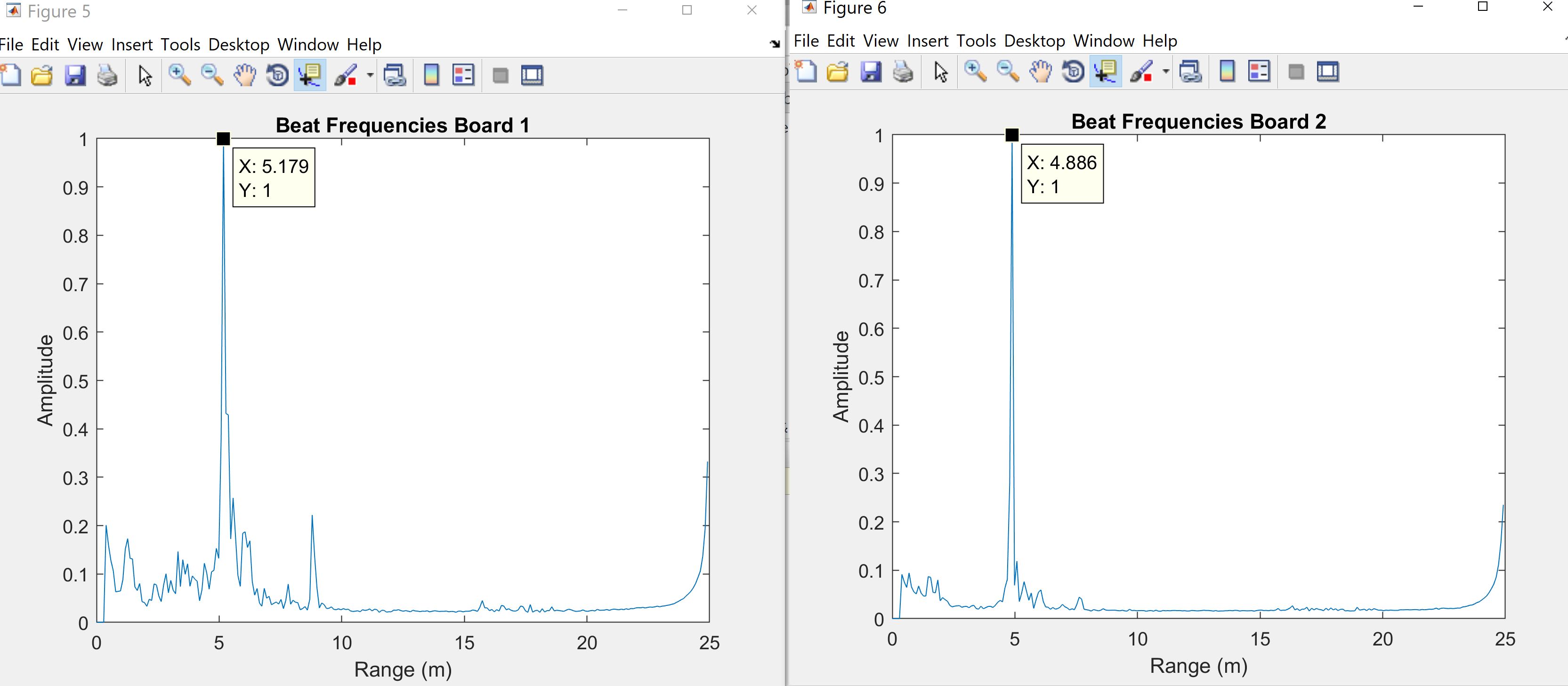
"I have two different AWR2243 boards, including the latest which has a sticker shown v2. The range estimations are different when using the boards under same test conditions. The offset starts from few samples and it gets higher depending on the location of the target.
I have no idea why this is happening. Is this expected?"

Please see attached the plots for different boards. As seen, boards are estimating different ranges (or peaks) while the real range is same for both. Thus during this experiment., we replaced the boards to make sure range will be unchanged

"

Thank you and looking forward for your kind response.

Regards,

Maynard

  • Hello,

    Just a quick question, do you know if the boards have been calibrated by the customer before this experiment?

    Sometimes, because of imperfections in antenna layouts on the board, there is a need to compensate for bias in the range estimation and receive channel gain and phase imperfections, which is basically called calibration. Please ask your customer to use a corner reflector and calibrate both the devices.

    You can also refer to the below threads for some details : 

    You can also refer to various threads on this forum which highlight the procedure (if that is also needed).

    Let me know if you require more details.

    Regards,

    Ishita

  • Hi Ishita,

    Below is the response of the customer.

    Isn't this mismatching the impact from ramp nonlinearity on the IF signal as it increases by range?

    Regards,

    Maynard

  • Hello Maynard,

      I assume you are using the same configuration on board the boards, what is your range bin step size in your configuration?

    Regards,

    Vivek

  • Hi Vivek, 

    I just received information from customer the following data.

    ADC size is 256, fc=77 GHz, fs=10 Msps, alpha=5.9964e+13 Hz/s, this leads to a range resolution of 0.0977m.

    Regards,

    Maynard

  • Hello Maynard,

    Are you using mmwave studio to configure the device and DCA1000 to capture the board? If yes have you tried to post process using the processing scripts in the mmwave studio?

    I suspect it might be either a data capture or data processing issue. I assume you are using complex 1x mode. At the end of the spectrum, closer to the band edge you should have seen a LPF kind of response with the power level reducing. But you are seeing a rise there, hence I suspect either a data capture or processing issue.

    Regards,
    vivek