This thread has been locked.

If you have a related question, please click the "Ask a related question" button in the top right corner. The newly created question will be automatically linked to this question.

AWR1843BOOST: Can we increase the horizontal range for MRR mode by tuning the configuration parameters?

Expert 2050 points
Part Number: AWR1843BOOST

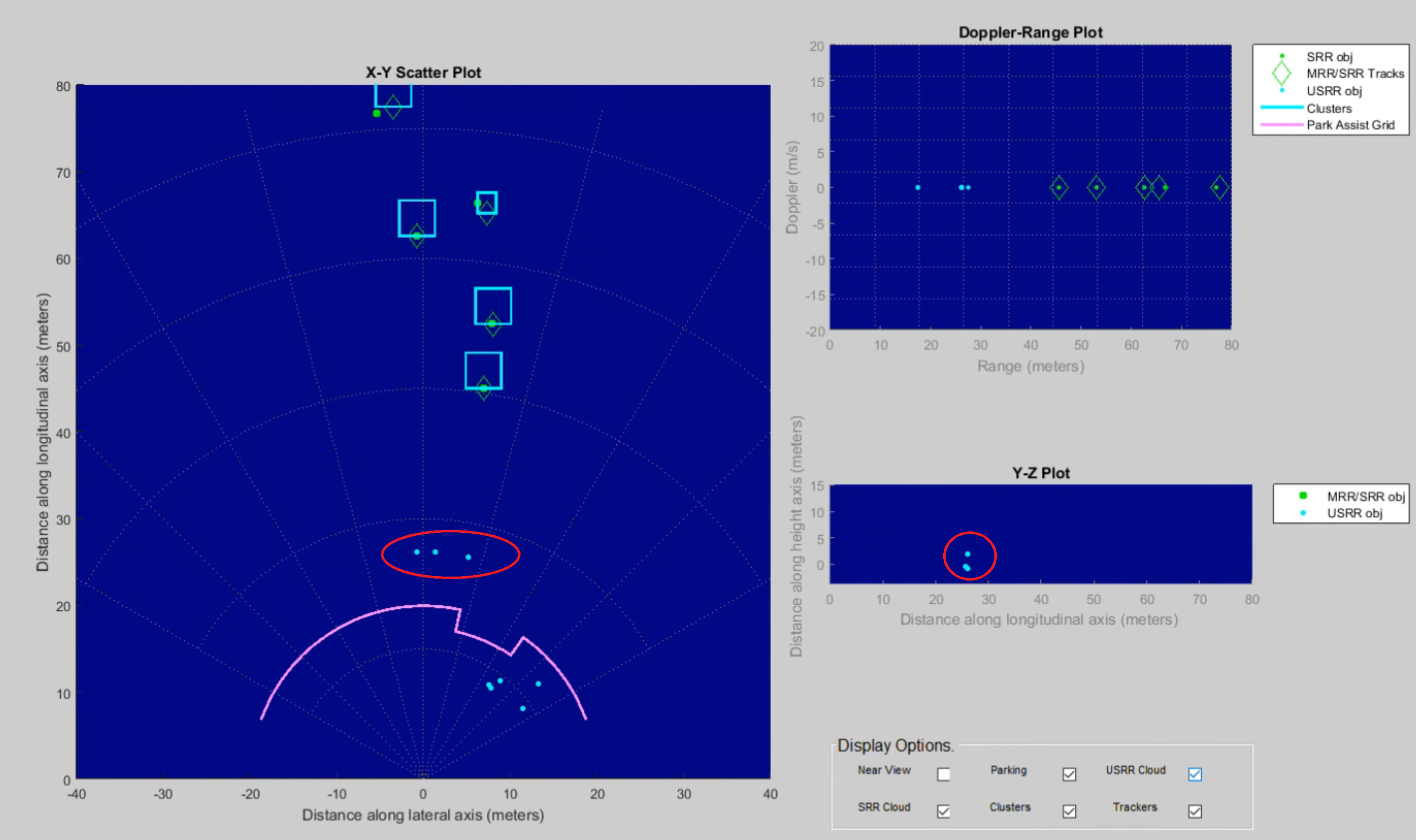
To my understanding, the distance and horizontal angle are tradeoff.  For our automotive use case, we only need the equipment to be able to detect objects within 50 meters. But hope his azimuth angle reaches 135 degree.

Based on the lab00007 MMR demo, can we achieve this goal by adjusting the configuration parameters?

  • Ree,

    The azimuth field-of-view is a function of the antenna pattern on the AWR1843BOOST. This particular antenna was designed to maximize the azimuth plane while still providing a relatively smaller field-of-view in the elevation plane.

    Modifying the configuration parameters would have an impact on the maximum range achieved by the sensor. It would not have an impact on the azimuth field-of-view.

    Regards,
    Kyle

  • Thanks Kyle,

    I tested MRR mode and USRR mode using AWR1843BOOST EVM and lab00007MMR demo. From my test result, I can see the MRR's FOV in the azimuth plane is about -30~+30 degree. Is it correct?

    It seems USRR mode has larger FOV in azimuth plane. But USRR makes wrong detected objects due to ground reflection. Can we tune configuration parameters to

    1. increase the maximum range of USRR 

    2. remove wrong detected objects as much as possbile

    ?

    Regards

  • Ree,

    The antenna pattern on the AWR1843BOOST is designed to have an azimuth resolution of +/-60 degrees.

    Increasing the maximum range of the USRR profile will come at a cost of range resolution. The differences between the MRR profile and USRR profile and centered around the idea that the MRR profile is used to resolve targets at greater distances (up to 150 meters) while the USRR profile is used to resolve small differences in range between objects close to the sensor.

    Increasing the maximum range would involve decreasing the bandwidth used in the USRR slope profile, would would have an impact on the range resolution.

    With regards to the ground reflection, it is possible to tune these objects out based on the height of the sensor relative to the ground and the z coordinate of the reflected object. If the z coordinate is negative and approaches (or exceeds) the height of the sensor, then this value could be removed as a ground reflection. This could be done either in the target code or in the visualizer.

    Regards,

    Kyle

  • Thanks you very much Kyle.

    Could you please explaint about this more? "If the z coordinate is negative and approaches (or exceeds) the height of the sensor, then this value could be removed as a ground reflection."

    I did below test. The detected objects in red circle are ground reflections because in reality, there is no object at those locations. In Y-Z plot, one detected object's z coordinate is few meters higher than the height of sensor.

  • Ree,

    Let's say for example that the sensor is placed 1 meter above the ground. And then the radar displays a detected object with a z coordinate of -1.2. This detection would actually be below the true ground value. So this type of detection should be filtered out since there is a detected object below the ground level which would not be of interest in this particular case.

    It looks like in your case, a couple of the detections you circled in red have a z coordinate less than 0. Now depending on the height of your sensor, these would indicate ground reflections. You could choose to filter these detections out in the MATLAB GUI based on their z coordinate values.

    This could also be impacted if there is any tilt in the sensor. The goal would be to have the sensor perpendicular to the ground.

    Regards,

    Kyle

  • Thanks Kyle,

    Could you also please tell me what is the elevation resolution the AWR1843BOOST is designed to have?

    Regards

    Ree

  • Ree,

    Please refer to the image above from the AWR1843BOOST EVM User Guide. This section from the User Guide should provide the exact answer that you are looking for.

    Regards,

    Kyle