This thread has been locked.

If you have a related question, please click the "Ask a related question" button in the top right corner. The newly created question will be automatically linked to this question.

MMWCAS-DSP-EVM: MMWCAS-DSP-EVM: Data Capture in MMWCAS DSP and RF EVM

Part Number: MMWCAS-DSP-EVM

Hello, 

I'm trying to bring up MMWCAS DSP and RF EVM.

Following these threads ( )  it seems I'm able to record required number of frames.

My question is more regarding the results I obtain, which doesn't correspond to the setup and moreover doesn't really change..

Settings are:

I run first Cascade_Configuration_TestSource.lua:

-- Profile configuration
local profile_indx = 0
local start_freq = 77 -- GHz
local slope = 79 -- MHz/us
local idle_time = 5 -- us
local adc_start_time = 6 -- us
local adc_samples = 256 -- Number of samples per chirp
local sample_freq = 8000 -- ksps
local ramp_end_time = 40 -- us
local rx_gain = 48 -- dB
local tx0OutPowerBackoffCode = 0
local tx1OutPowerBackoffCode = 0
local tx2OutPowerBackoffCode = 0
local tx0PhaseShifter = 0
local tx1PhaseShifter = 0
local tx2PhaseShifter = 0
local txStartTimeUSec = 0
local hpfCornerFreq1 = 0 -- 0: 175KHz, 1: 235KHz, 2: 350KHz, 3: 700KHz
local hpfCornerFreq2 = 0 -- 0: 350KHz, 1: 700KHz, 2: 1.4MHz, 3: 2.8MHz

-- Frame configuration
local start_chirp_tx = 0
local end_chirp_tx = 11
local nchirp_loops = 64 -- Number of chirps per frame
local nframes_master = 5 -- Number of Frames for Master
local nframes_slave = 5 -- Number of Frames for Slaves
local Inter_Frame_Interval = 100 -- ms
local trigger_delay = 0 -- us
local trig_list = {1,2,2,2} -- 1: Software trigger, 2: Hardware trigger

and then Cascade_Capture.lua


capture_time = 2000 -- ms
inter_loop_time = 2000 -- ms
num_loops = 1

n_files_allocation = 4
data_packaging = 0 -- 0: 16-bit, 1: 12-bit
capture_directory = "Cascade_Capture_22xx97"
num_frames_to_capture = 0 -- 0: default case; Any positive value - number of frames to capture

framing_type = 1 -- 0: infinite, 1: finite
stop_frame_mode = 0 -- 0: Frame boundary, 2: Sub-frame boundary,
-- 3: Burst boundary, 4: HW/Sub-frame triggered

Setup:

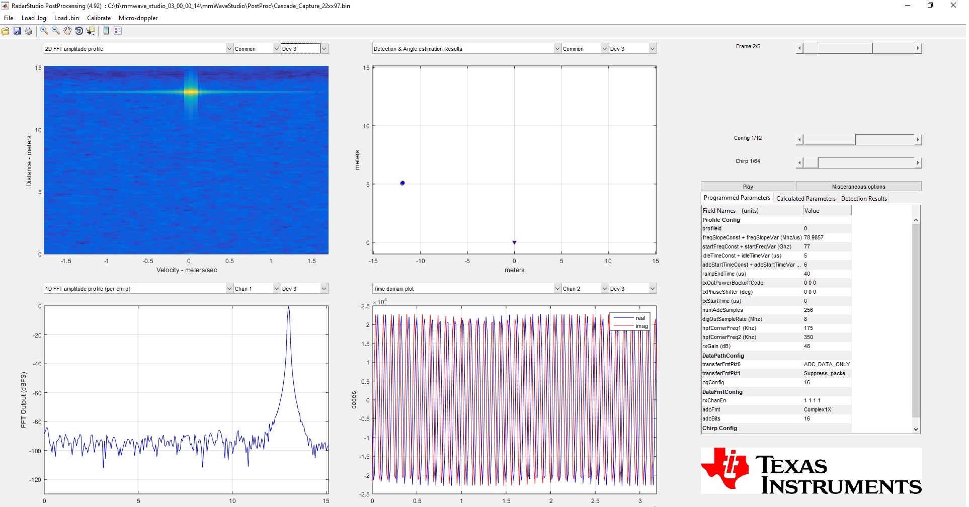
a) the setup on the table facing the ceiling (around 2.5m) I have

For Dev1 and Dev 2 results are the same:

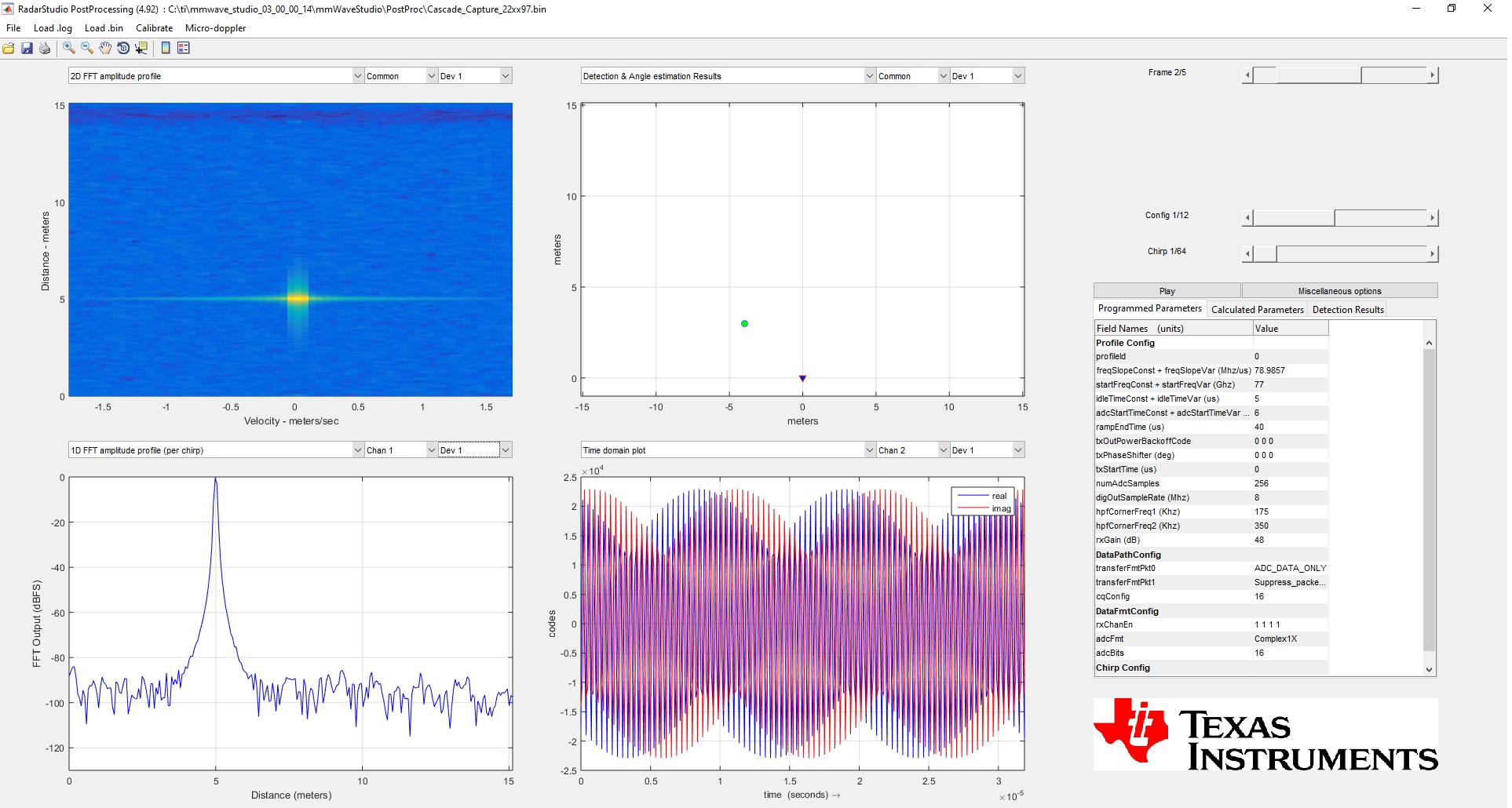
For Dev3 and Dev4 results are the same::

b) the setup on the table facing a corner reflector around at 0.5m range

Results are identical for Dev1 and 2 and Dev3 and 4 to a human eye.

Any support please?

Thanks

Best

Maxim

  • Hi,

    Will be able to review your question and get back to you before Monday

    thank you
    Cesar

  • Hello Maxim,

    From your setup descriptions, I can see you want to capture real object data, like the ceiling or a corner reflector. I see you're running the "Cascade_Configuration_TestSource.lua" script. Now since you've enabled test source capture, you won't be able to observe any of the real objects. Test source is just used to simulate the presence of an object at the specified coordinates.

    Please disable the test source and then try again.

    Let us know your observations.

    Regards,

    Ishita

  • Hello Ishita, 

    Thanks for direction, now all seems to work, at lease I see correspondence to the environment.

    What I'm still confused is how to calculate n_files_allocation? It says "Pre-allocate as many files as needed based on (size_per_frame * number_of_frames) to be captured."  Where do I find size_per_frame ?

    And last point is on calibration:

    1. How should I do that? There is a "Cascade_Monitoring_Example.lua", but what is the output of this script? should I feed it somewhere? Do I need to make a particular setup for that?

    2. During PostProc there is also a possibility to make a calibration of pre-existing recordings, but for that it asks of a dedicated measurement with a corner reflector and single TX. In which mode should I do this recording and is there a script for that?

    3. There is also "RF Init Calibration Configuration", which is done during the configuration, e.g. in MIMO or TXBF scripts, does it use some predefined calibration?

    4. How this 'post-processing' (from point 2) calibration is different from "RF Init Calibration Configuration" in point 3?

    Thanks!

    Maxim 

  • Hello Maxim,

    1. Total Size in Bytes (1 Frame) = no_of_Chirps * NumADC_Samples * 2(I/Q) * NumRX_channels * 2(16bit)

    2. Cascade_Monitoring_Example.lua script configures various monitors in the device. Based on your usecase, you can decide what all monitors you want to use. For cascade setup, the reports will be stored in the "PostProc" folder under the names MonitoringReport_0.txt/ MonitoringReport_1.txt/ MonitoringReport_2.txt/ MonitoringReport_3.txt for all the four devices.

    Just remember to enable the logging of the reports and use the appropriate reporting mode. Please refer to mmWave ICD for details on each of these monitors and the reporting modes.

    I will get back to your other questions by Monday.

    Regards,

    Ishita

  • Thanks, Ishita!

    BR

    Maxim

  • Hello Maxim,

    Regarding your previous concerns,

    RF Init calibration configurations refer to the Boot time calibrations in the device. That is done to stabilize the radar front end performance across temperature and process. You can read more about it the following Application note :

    Self-Calibration of mmWave Radar Devices (Rev. A)

    Whereas the post-processing calibration that you're talking about is mainly to eliminate the inter-channel and phase mismatches. 

    For details on this, you can refer to the mmwave_studio_cascade_user_guide.pdf and AWRx_TX_Channel_Calibration_Script_User_Guide.pdf ( C:\ti\mmwave_studio_03_00_00_14\mmWaveStudio\MatlabExamples)

    Regards,

    Ishita