This thread has been locked.

If you have a related question, please click the "Ask a related question" button in the top right corner. The newly created question will be automatically linked to this question.

IWR6843: Reg. IWR6843 UART pin connection

Part Number: IWR6843
Other Parts Discussed in Thread: , UNIFLASH

Hi Team.

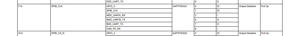
I am working on the IWR6843 mmwave sensor with a custom board. I have connected RS232 Tx/Rx to UART2 as a command port. MSS_LOGGER_Tx, MSS_LOGGER_Rx, BSS_LOGGER_Rx, DSS_LOGGER_Rx connected to UART1 as a data port. but I am not getting any data. can you correct me if the connections are wrong? For commands port which pins are mandatory? For the Data port, which connections are mandatory? please help me with this.

Regards,

Srikanth

  • Srikanth,

        Logger pins can be pin muxed on to many different ports. Which application you are trying to run? 

    Have you reviewed the IWR6843ISK board? Connection should be similar to that.

    We would need schematic/Layout to comment and What are the differences that are done as compared to IWR6843ISK board? 

    Thanks and regards,

    CHETHAN KUMAR Y.B.

  • Hi Chethan,

    Yes, I have reviewed the IWR6843ISK board mentioned above message. it is the same as the IWR6843 mmwave sensor. why MSS, BSS, and DSS Logger_Rx is required? Is there any specific reason these 3 Rx pins are shorted? Can you please give me some gudience.

    Regards,

    Srikanth

  • Hi Chethan,

    Yes, I have reviewed the IWR6843ISK board mentioned above message. it is the same as the IWR6843 mmwave sensor. why MSS, BSS, and DSS Logger_Rx is required? Is there any specific reason these 3 Rx pins are shorted? Can you please give me some guidance. 

    Regards,

    Srikanth

  • Srikanth,

        There should be some difference, it could be either on the hardware or on the software side, that we should identify why it's not working.

    MSS, BSS, DSS logger signals are not shorted, but they are pin multiplexed. These are debug pins to provide the data out in UART ports. 

    mmWave sensor has multiple cores are present that are represented Master subsystem (MSS), BSS (buil)

    Essentially these are UART ports that are available to bring data out from different part of processor cores.

  • Srikanth,

        Sorry, previous post was abruptly sent,  

       mmWave sensor has multiple cores that are represented Master subsystem (MSS), BSS (Built in self test subsystem),  DSS (Dsp sub system), each of the subsystem UART ports could be pin muxed on single pin as shown in the above table. 

    In the demo context MSS_UART_Tx UART port is used to send out processed data from the MSS processor core.

    If the Hardware is same as IWR6843ISK and used the SDK binary as is it should have worked. Hence request is to identify difference between the two system. 

    Thanks and regards,

    CHETHAN KUMAR Y.B. 

  • Thanks for the update chethan,

    As per your context can I assume IWR6843 mmwave sensor TLV data coming from the MSS_LOGGER_RX pin only. I tried with this combination but I didn't see any TLV data. I will explain my connections to IWR6843 (Custom board with IWR6843 QG mmwave sensor), can you tell me my connections are correct or wrong. If there is any connections are required in function mode to read the  TLV data from IWR6843. please let me know. see the below points.

    • RS232_Rx / Tx pins are connected to the UART port of the custom board (ex. UART2)
    • MSS_LOGGER_TX and MSS_LOGGER_RX pins are connected to another UART port (Ex. UART1)
    • For Function Mode, SOP[2, 1] pins are connected to GND, and SOP[0] pin is connected to 3V3.
    • For the whole circuit power supply, I'm taking from an external DC power supply with 3.3V.

    Regards,

    Srikanth

  • Srikanth,

       In  IWR6843ISK using  TI demo flashed on the devices sends out data on MSS_LOGGER_Tx pin not on MSS_LOGGER_RX. And this MSS_Logger_Tx pin need to be connected to RX port of the UART interface. 

    You cannot permanently tie the SOP lines, From the above description, it appears that device is in functional mode and it's trying to read the content from the QSPI flash. If the QSPI flash is empty then boot failure would happen and device will not be operational.  

    Could you please confirm were you able to successfully flash the device?

    I think you have already reviewed this, but just for the reference, below boot loader application note is provided.

    IWR6843 Bootloader Flow https://www.ti.com/lit/an/swra627/swra627.pdf 

    Thanks and regards,

    CHETHAN KUMAR Y.B.

  • Dear Chethan,

    As per the ticket https://e2e.ti.com/support/sensors/f/1023/p/969239/3603063#3603063, and above description, let me put more concrete info

    We are able to flash IWR6843

    In case of functional mode, the following connections are performed

    a) WARM_RESET pulled up with 3.3V

    b) SOP2, SOP1 is connected to ground, SOP0 is connected to 3.3V 

    c) MSS_UART_TX is connected to UART_RX

    d) nRESET is initially pulled high, then pulled low, followed by pulling high

    a, b and c steps are hardware connections. 

    d is done in SW.

    In the above scenario, we are not seeing any data thrown from IWR6843.

    Can you please answer below questions:-

    1) I have some doubts on (d) step - Is the step correct

    2) Any other settings to be done?

    3) Is there way we get debug logs from IWR6843 so that we understand what is happening? Since there are no logs, it is becoming tricky to find what is missing.

    Thanks

    Chandra

  • Chandra,


    Few care about that need to be noted, All the I/O supplies other than listed below should not be driven externally without VIO supply. 

    If you are connecting the UART pins through external USB to UART interface, there may be possibility of UART pin being driven without VIO supply, when power cycling the board. This must be avoided. 


    Couple of other pointers to debug are:

    1) Is there any NERROR asserted low (This indicates some hardware fault) that must be debugged

    2) Probe the QSPI lines to see flash reading happening or not. You should be able to see complete flash downloading activity.

    3) You could connect to JTAG and see if the processor and check processor cores are operating fine or not. 

    4) You could review hardware bring up checklist from the below link and see any anomaly w.r.t to expectations.  

    https://www.ti.com/lit/zip/swrr161 

    Thanks and regards,

    CHETHAN KUMAR Y.B.

  • Chandra

  • Chandra,

        Thanks for the confirmation, Above steps are correct. Yes, I meant NERROR_OUT. 

    Also you could probe QSPI interface and MSS_LOGGER interface on a scope or Logic analyzer, and compare the results with IWR6843ISK EVM waveforms and will help to narrow the problem.

    Thanks and regards,

    CHETHAN KUMAR Y.B.

  • Thanks for the update Chetan.

    we followed all the above connections as you said. but still, we're not getting TLV data from IWR6843. On top of the connection, we checked PMIC pin to a high state. it is not helpful. Is there any other process to get the TLV data? Please do the needful.

    Regards,

    Srikanth

  • Srikanth,

       If the hardware is same as IWR6843ISK then it should have worked. There is a difference between the IWR6843ISK.

    Without identifying the differences we will not be able pin point the problem area. For further suggestion, we may have to review the schematic and Layout in detail.  

    Thanks and regards,

    CHETHAN KUMAR Y.B.