This thread has been locked.

If you have a related question, please click the "Ask a related question" button in the top right corner. The newly created question will be automatically linked to this question.

TDC1000: Improving fluid level measurement distance.

Part Number: TDC1000
Other Parts Discussed in Thread: TUSS4470, PGA460, TUSS4440, BOOSTXL-TUSS4470

Hello,

I am trying to create a relatively simple device, a fishfinder. The device shall float on water, the transducer and the PCB board are located within its casing. I would love the device to read the depth of the body of water. I would like to utilise the TDC1000, my issue is one its features: 

  • Measurement Range: Up to 8 ms

which does not appear anywhere else on the datasheet. Is it possible to override this feature? Based on this post , the maximum range is 5.9 meters, whereas I need it to be around 15 meters. Should I switch devices?

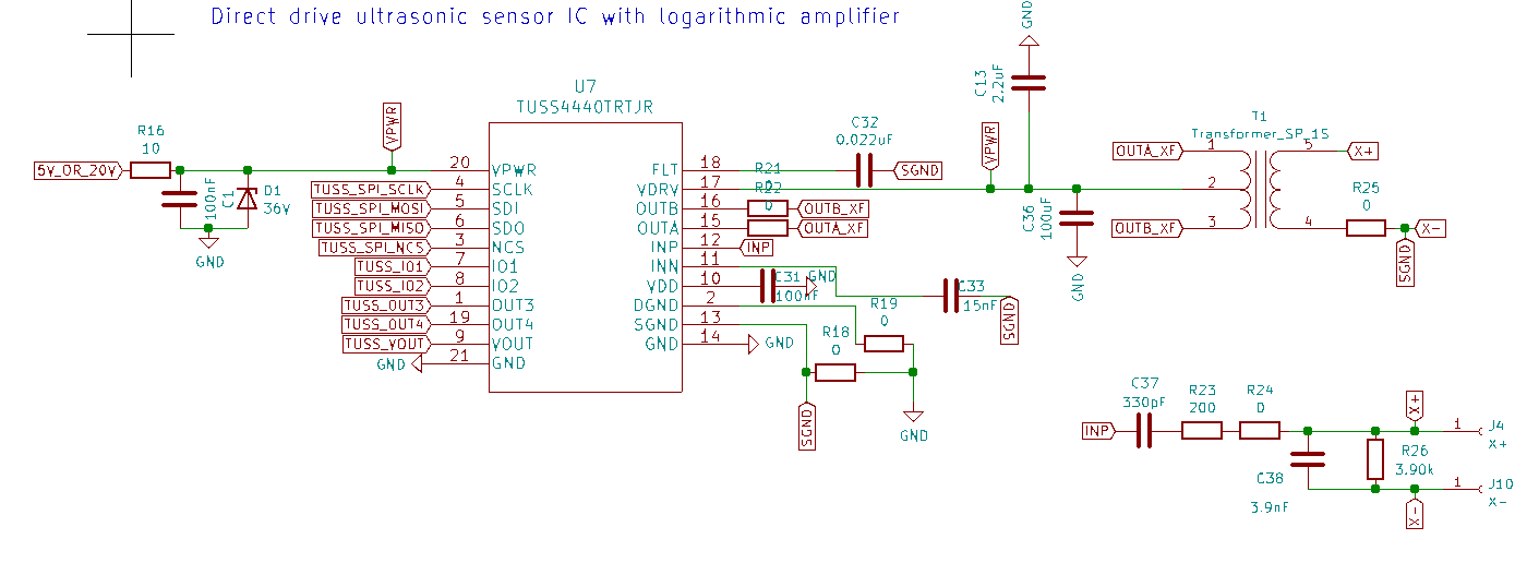
I found also this device, which has the same measurement range. Could someone explain the limitation of those AFE's?

  • Philip,

    The 8 ms value is based on the default test parameters used in the specification table of the datasheet.  Here the divided clock frequency is 1 MHz.  With this frequency, the resulting value for T0 is 1 us.

    Section 8.4.6.2 of the datasheet describes the listen timing for the device:

    Using 1 us for T0, 1023 (x3FF) for TIMING_REG, and the TOF_TIMEOUT_CTRL set to the maximum value of 1024*T0, we can calculate the total ECHO Listen Time.

    (1023-30) * 8 * 1 us + 2^(1024* 1us) * 128 * 1 us = 8.072 ms.

    With lower input frequencies, it should be possible to extend this listen period, but it is not recommended to hold the RX in listen mode for longer than 100 ms.

    It may be desirable to disable the timeout function to maximize range.  I would also caution that as the range increases that the returning echo will dampen more. It will be most ideal to power the device to the maximum supply voltage to increase the outgoing pulse magnitude.

    The TDC receiver does not offer as much gain as some of our other devices such as PGA460 or TUSS4470 which may be better suited for this application depending on the transducer frequency.  We typically recommend TDC-1000 for smaller tanks or enclosures. One transducer option that can work with both PGA460 or TUSS4470 for underwater applications is the Prowave 200LM450.

    I am not familiar with the Maxim portfolio and am not able to comment on their devices.

  • Hello Scott,

    thank you so much for your swift response, and providing the calculations for the TOF for the device.

    How would you approach picking the right transducer frequency for our application? We want the angle to be as narrow as possible, and the max depth shall be 15 meters. Would you say those ranges will be too difficult for the TDC1000 to achieve? Based on this device , they are using 675 kHz to achieve 100 meters. 

    Our device must be very energy efficient, as it will be batterry powered, but we want to incorporate the 30V 50% boost that is in the application notes.

    Based on this answer, the PGA460 should not be used in fluids, is it the same case for the TUSS4470?

    How do you calculate the LNA and PGA values for a frequency?

  • Philip,

    The reason PGA460 was specifically called out for air coupled applications in the response you found is that there hasn't been any characterization of the device for liquid coupled situations. While we might be able to adjust the listen window for TDC1000, I do not expect that you will be able to transmit and receive an ultrasonic burst effectively through water at that range.   

    We do have an application note for TUSS4470 which compares it to TDC1000 for a water coupled example (section 4.2.3), but not at the scale you are trying to achieve.  Also, we have verified functionality of both PGA460 and TUSS4470 in an air coupled environment using the transducer mentioned above, which was designed for liquid coupled applications.  

    https://www.ti.com/lit/an/slda053/slda053.pdf

    TDC1000 cannot generate as much output power nor is it as sensitive as either PGA460 or TUSS4470.  Both should be better suited for this application given the range you are trying to achieve.

    This application note may help provide more guidance on your transducer selection:

    https://www.ti.com/lit/an/slaa907c/slaa907c.pdf

    The challenge with selecting the transducer and operating frequency will be a tradeoff between your viewing angle and depth.  Higher frequencies will attenuate faster while lower frequencies widen the viewing angle. I expect from the product you linked, that they are only able to achieve maximum depth with the 100 kHz wide angle. You will also want to be sure you use a closed top transducer which will be protected from the environment.

    Thanks,

    Scott

  • Thank you so much for your answer! I decided to go with the TUSS4470 as I believe it will fit best my application. I also chose 2 transducers, 200kHz and 500kHz, once I start testing I will report the outcome, hopefully helping other people. I Would love to make sure that the schematic below is correct. I will be supplying 20V to the VPWR pin to achieve better depth.

  • Philip,

    You currently have TUSS4440 installed instead of TUSS4470.

    You do not appear to be driving the VDD pin in this schematic.  Please be sure to connect it to a supply voltage to match your digital inputs.

    Otherwise this looks to be a very close copy of what is in the BOOSTXL-TUSS4470 board.  One thing I notice is that on FLT you have selected a capacitance equal to the sum of all capacitor options on the EVM. In your end application you will likely want just one capacitor here for size restrictions, but you may want to be prepared to change these devices depending on your transducers.  

    Thanks,

    Scott