This thread has been locked.

If you have a related question, please click the "Ask a related question" button in the top right corner. The newly created question will be automatically linked to this question.

MMWAVEICBOOST: Sensors forum

Part Number: MMWAVEICBOOST
Other Parts Discussed in Thread: IWR6843, IWR6843AOPEVM, CC2640R2F, UNIFLASH

Hi TI expert

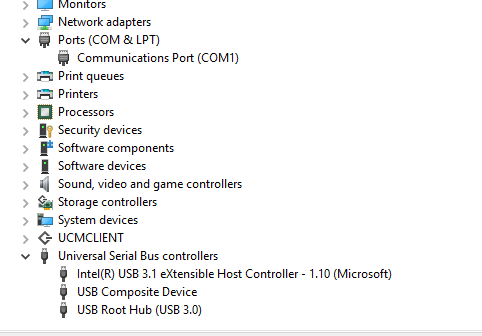
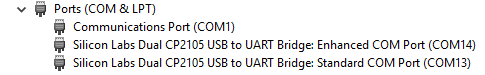
I am trying to connect my mmWAVEICBOOST board (with my IWR6843 module plugged onto it) to my desktop computer through USB cables. Previously with the cables TI provided, the connection was successful, but currently I am away from where I work and forgot to take those two cables with me, so I am using other cables for the connections. These cables are also USB to micro-USB cables (used for charging my android cell phone), which can be plugged into the FTDI and XDS110 ports of the mmWAVEICBOOST board, but my desktop computer cannot detect the board. The picture of the connection and the Device Manager screenshot of my desktop computer are attached.

  • Hello Li Chen92,

         FTDI USB port is not to be connected to PC. FTDI interface on mmWaveICBOOST board is not yet productized. 

    Please follow below training guide for connecting EVM for connections and jumper settings and switch settings. 

    https://training.ti.com/hardware-setup-mmwaveicboost-and-antenna-module

    Thanks and regards,

    CHETHAN KUMAR Y.B.

  • Hi CHETHAN KUMAR Y.B.

    Thank you for your replying.

    I have now connected the board to the PC correctly, with only the XDS110 port connected to the PC through micro USB. I have also followed the trainig guide mentioned in your reply. However, as I proceeded to around 4:30 of the video, it asked me to toggle the NRST switch. The correct board performance should be: The LED is on when power is applied to the board, and when the NRST switch is pressed and released, the LED should be first off, and then on. However, the LED on my board is always off, ever since I apply the power to the board. No matter I press or release the NRST switch, the LED is off. I have attached a picture of my board, for your reference.

    Thank you very much for your help and looking forward to your reply!

    Best regards,

    Thomas

  • Thomas,

        Thank you for the confirmation and updating the setup. 

    Even without AOP board, Do you see reset LED is off? 

    Thanks and regards,

    CHETHAN KUMAR Y.B.

  • Hi CHETHAN KUMAR Y.B.

    Thank you very much for your reply! I have unplugged the AOP board, and the LED light is now on. Please check this picture attached.

    Best regards,

    Thomas

  • Hello Thomas,

        It may be possible IWR6843AOPEVM could be pulling the reset line low. Also AOP EVM used is older version.

    Could you please check IWR6843AOPEVM works in standalone mode fine? switch settings of the older version of EVMs are shown in the EVM user guide under section 6.5. This doesn't need mmWaveICBOOST board or external power supply, you could operate with just USB cable. 

    Even standalone mode is not working then you may have get a new EVM.

    For the latest EVM operating standalone Video link you could find from the below link.

    https://training.ti.com/hardware-setup-iwr6843isk-and-iwr6843isk-ods

    Thanks and regards,

    CHETHAN KUMAR Y.B.

  • Hi CHETHAN KUMAR Y.B.

    Thank you for your replying.

    When the IWR6843AOPEVM board is connected to the PC directly, the temperature of the board, especially the antennas, rises, and it gets hot in minutes. I hope this information might be helpful in troubleshooting the issue. Thank you very much!

    Best regards,

    Thomas

  • Hi CHETHAN KUMAR Y.B.

    Thank you for your replying.

    One more issue, I have tried plugging the EVM board directly to my PC, and it looks like the connection is successful, with 3 LEDs on. Please see my attached picture of the board. Additionally, I have also checked the Device Manager of my PC, and under the "Ports" section I noticed that two more connections named "Silicon Labs Dual CP2105 USB to UART Bridge: Enhanced COM Port" have appeared, which I think means that the connection is successful. Please also find the attached screenshot of my Device Manager.

    Therefore, since I currently don't have an SICP2015, nor a CC2640R2F in hand, and all I have besides the IWR6843AOPEVM is the MMWAVEICBOOST board, whose debugging tools I hope to use for developing my applications. What you suggest me to do for the next step to ensure a successful working when the EVM board is connected to the MMWAVEICBOOST?

  • Hi,

    You can run functional and flashing mode, meaning program via UART/UNIFLASH and run the demo using just the IWR6843AOPEVM. The "Silicon Labs Dual CP2105 USB to UART Bridge: Enhanced COM Port" is the on board SICP2015.

    see section 6.7.1 of user guide

    https://www.ti.com/lit/ug/swru546d/swru546d.pdf

    Regards,

    Charles O

  • Hi Charles O

    Thank you very much for your reply! It's great to hear that I use the IWR6843AOPEVM in the standalone mode to run some demo, and at least I have something to play with now. However, what will be the difference between using the IWR6843AOPEVM in the standalone mode and using it when plugged into the mmWAVEICBOOST board? Will there be any performance degradation, and will be there be any difficulties or inconveniences with debugging when using the EVM board in the standalone mode?

    Thanks and Best regards,

    Thomas

  • Hi,

    You cannot debug with just the IWR6843AOPEVM, the XDS110 JTAG debug on the MMWAVEICBOOST is needed for debug.

    Regards,

    Charles O