This thread has been locked.

If you have a related question, please click the "Ask a related question" button in the top right corner. The newly created question will be automatically linked to this question.

PGA302 : PGA302 Hall Sensor Drift

Part Number: PGA302
Other Parts Discussed in Thread: TMCS1100, TMCS1101

Hello,
I am developing a project using magnets.
Magnet current is amplified by PGA302 and used.
However, there is a problem that the value increases without any action at the point of 0.
I think it is a drift phenomenon over time.

The products I have to develop have to be very precise.

I need a product that can keep the value constant even if it is still using magnets.
In addition, it must be a product that requires automotive certification.
We are looking at TMCS1100, TMCS1101 products.

I am making a product in which mcu works by reading Alnico magnets with a Hall sensor.

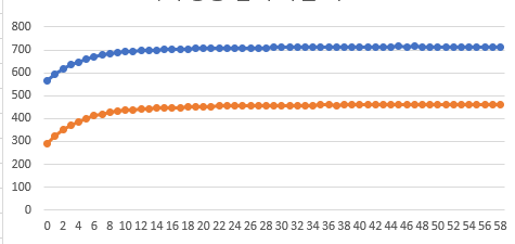
I added additional graphs.
The x-axis is time and the y-axis is the AD value read from mcu.

There is a problem that the value keeps rising for about 0~10 minutes on the graph.
Can the PGA302 solve this problem?

I need a product that can keep the value read from the Hall sensor.
Please introduce a product that you are satisfied with.

thanks.

  • Hello Seok,

    Just to clarify, this is the raw data directly from the PADC_DATAx registers? What is the second set of data included in the graph? Are these just two measurements done at different times superimposed on one another?

    What is the magnitude of the signal to the VINPP and VINPN inputs, and is the data from the hall sensor in this example? To determine if this is due to the PGA302 itself, I recommend applying a fixed voltage that matches the output of your hall sensor, and perform the measurement again over the same time period. If there is still a drift, this may be due to some self-heating affecting the measurement. I would also monitor the internal temperature sensor output at the same time.

    Regards,

  • The graph above is the graph read from MCU.
    Since there are 2 channels, 2 graphs have appeared.

    VINPP is 10mV, VINPN is -10mV.
    The value of the magnet was read with the Hall sensor.
    Hall sensor is connected to the input part of PGA302.
    And this is a graph taken with the PGA302 EVM.
    The magnet is measured at the S pole end and does not move.

    However, the AD graph of the PGA302 is moving.

    The AD of the PGA302 is moving, but the DAC must be constant.
    The value should always be output consistently according to the position of the magnet.

    Is there a way to set it on the PGA302?

    thanks.

  • Hello Seok,

    Is the hall sensor output/VINPP/VINPN input measured separately for the entire time period? My suggestion is simply to remove the ADC input as a variable. Even if the hall sensor is very stable, unless it is also measured by another instrument across the same time period it can't be ruled out as a potential cause for the drift. The simplest way to do this would be to use an external power supply to provide the input to the PGA302. 

    And to further clarify about the two sets of data, you mention two channels. So you have 2 separate PGA302s that are feeding data into your MCU?

    The DAC output will always be relative to the ADC input. There is temperature and nonlinearity compensation available through the calibration coefficients, but there is no time component. Unless the drift is caused by temperature changes and can be calibrated out, the DAC output will show a similar drift over time.


    Regards,

  • It uses two Hall sensors, two PGA302s and one MCU.
    The MCU is used with two Hall sensors.
    1 Hall sensor and 1 PGA302 are set.
    All are used individually.
    Thank you for answer.
    I didn't understand about removing the ADC input into a variable.
    Please let me know in detail.

    Please introduce me if there are other models that can further eliminate this problem.
    Magnets, Hall sensors, and PGA are essential.

    thanks.

  • Hi Seok,

    I don't mean to remove the hall sensor from your application, but for the purpose of debugging the system to find the source of the drift it is best to have a known input. This can be done in two ways. You can supply a fixed voltage to the inputs by using a voltage supply, or you can measure the output of your hall sensor (the ADC input) throughout the entire time period that you are recording the PGA302 data. When you know exactly what the input voltage is for the entire time period of the measurement, you can determine if the drift is coming from the sensor or the PGA302.

    Regards,