Other Parts Discussed in Thread: TDC7200
Hello,
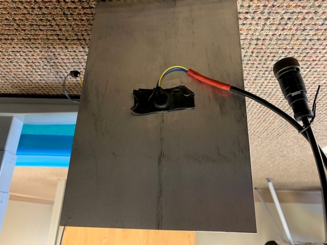
I am using a custom board that is intended to measure the thickness of very thick steel block (up to 360mm). Please see the attached pictures for an example (the example shows the sensor attached to an aluminum block though as this is used for initial testing)
The board uses TDC1000 and TDC7200 for capturing the time of flight. TX signal is raised to 24V.
The original thread, that this one is linked to, has nice steps to help figuring the setting of the above chips but I appreciate if I can get some feedback on the below points as the trials that has been done so far does not seem to provide good results.
1. Looking at the speed of sound in steel or aluminum, I see that normally the speed is listed in many websites mainly for 3 kind of waves, Longitudinal, Shear, and Extensional. I am not sure which one should I use in my calculations for these blocks. Please advice.
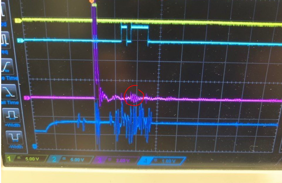
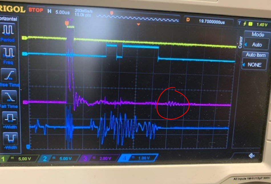
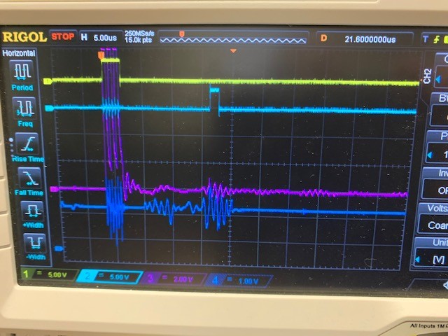
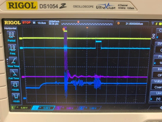
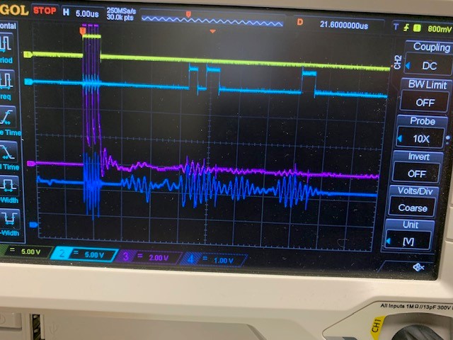
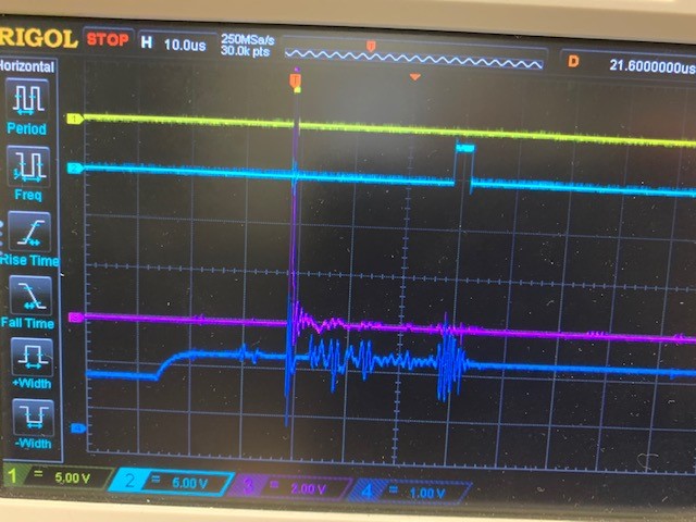
2. For some reason, I am getting the same waveforms regardless of the block thickness to which the US sensor is attached (please see attached waveform: Channel A is Start signal, Channel B is Stop, Channel C is the TX signal). One picture shows the whole sequence and and the other one is zoomed-in to see one of the echo and stop signals.
3. The sensor that I am using is 1MHz (SMD15T21R111WL). It is currently attached to the block using Scotch double sided tap in both sides (top and bottom). We will use appropriate epoxy in final application.
4. The settings of the TDC1000 are currently set to:
* Click divided by 8
* Num_TX =3
* NUM_RX=3
* ECHO_QUAL_THLD_125
* RECEIVE_ECHO_MULTI (for distance/thickness measurements)
* High bit of the TIMING_REG is set to 0x03 to enable standard mode. Force short time of flight is not set.
Your feedback is much appreciated.
Thanks!
George