This thread has been locked.

If you have a related question, please click the "Ask a related question" button in the top right corner. The newly created question will be automatically linked to this question.

IWR6843: Not able to boot-up IWR6843 mmWave sensor Board

Part Number: IWR6843

Hi,

We're working on IWR6843 mmWave sensor board using our own custom board. we monitor all the signals as per our knowledge including the CLK, Power, etc., we are sending commands which we captured on the oscilloscope as well. attached for your review. 

Below is the Working Image:

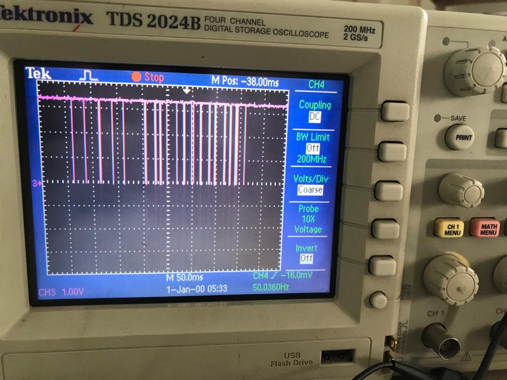
Below is the Not Working Image:


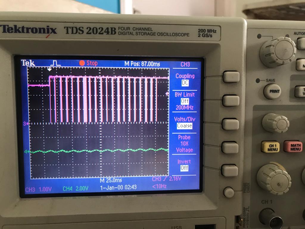
We're not sure which signals should be monitor and what should be their state. So we request you to provide us the list of the signal and their level need to be monitor.

Regards,

Srikanth

  • HI,

    What is the image you are sharing and what is the issue with the board?

    Regards,

    Charles O

  • Hi,

    We're working on custom boards for people count monitoring (mmwave_industrial_toolbox_3_6_2). we have 2 custom boards, one is FT4232 + IWR6843 mmWave sensor combination. the second one is ESP32 MCU with Wi-Fi + IWR6843 mmWave sensor combination.

    1. FT4232 + IWR6843 mmWave Sensor (Working Module)

    • In a previous conversation, I have shared the oscilloscope images. first, one is a working image with FT4232.
    • For this working module, we're using a GUI Matlab visualizer to send the config commands and we were able to see the data in the visualizer.
    • while sending config commands over GUI, we checked commands follow and captured oscilloscope image and shared the first image.
    • We observed, commands to commands some dealy is there, sometimes it is high delay and sometimes it is a low delay. is this my observation is right? if yes, how to generate and how much time delay is required to send the commands. In Matlab code didn't mention.

    2. ESP32 MCU with Wi-Fi + IWR6843 mmWave sensor (Not Working Module)

    • For this scenario, we develop the program, and sending the config commands below is the format.
    • printf("Commands execution is Started\n");

      const char *test_str[] = {"sensorStop\r",
                                             "flushCfg\r",
                                              "dfeDataOutputMode 1\r",
                                              "channelCfg 15 5 0\r",
                                              "adcCfg 2 1\r",
                                              "adcbufCfg 0 1 1 1\r",
                                              "profileCfg 0 60.6 30 10 62 0 0 53 1 128 2500 0 0 30\r",
                                               "chirpCfg 0 0 0 0 0 0 0 1\r",
                                              "chirpCfg 0 0 0 0 0 0 0 4\r",
                                             "frameCfg 0 1 128 0 50 1 0\r",
                                             "lowPower 0 1\r",
                                             "guiMonitor 1 1 0 0\r",
                                             "cfarCfg 6 4 4 4 4 16 16 4 4 55 67 0\r",
                                             "doaCfg 600 1875 30 1 1 0\r",
                                             "SceneryParam -6 6 0.5 6\r",
                                             "GatingParam 3 2 2 0\r",
                                             "StateParam 10 5 100 100 5\r",
                                             "AllocationParam 250 250 0.25 30 1 2\r",
                                             "trackingCfg 1 2 250 20 52 82 50 90\r",
                                             "sensorStart\r"
      };

      for(i=0;i<sizeof(test_str)/sizeof(test_str[0]);i++){
      uart_write_bytes(uart_num2, test_str[i], strlen(test_str[i]));
      printf("%s\n", test_str[i]);
      vTaskDelay(50 / portTICK_RATE_MS);
      }
      printf("Commands executation is Completed\n");

    • Second Image, we observed a working module waveform and this waveform is not the same, initially, this is generating low and sending the commands.
    • one more observation is a delay between the command to command is the same. but still, IWR6843 is not working.
    • I want to see the TLV data using ESP32 MCU with Wi-Fi module + IWR6843 sensor combination.

    We enabled the required pins as per the timing diagram. Please give me some guidance to get the TLV data.

    Regards,

    Srikanth

  • Hi,

    • On the ESP32 MCU with Wi-Fi + IWR6843 mmWave sensor what  peripheral interface is used, is it different from the FT4232 + IWR6843
    • I don't understand why the scope capture is expected to be  the same?
    • What is the waveform shown on the oscilloscope, is it SPI? UART TX? what is it?
    • When you say not working, what does that mean? 

    Can you please provide a more complete picture of the problem? 

    Regards,

    Charles O

  • Hi,

    • On the ESP32 MCU with Wi-Fi + IWR6843 mmWave sensor UART peripheral interface is used, is it the same as the FT4232 + IWR6843
    • Just we're thinking if the scope captured image is the same, so that we will get the TLV data. as per your assumption, if not the same but I am not getting any output data.
    • The waveform is shown on the oscilloscope is UART Tx, (Config commands)
    • Not working means, I interfaced everything but i am not getting any output TLV data from this device.

    Regards,

    Srikanth

  • Hi Srikanth,

    1. Are the working and failing device the same schematic and layout?
    2. If its the same does the failing module work with the FT432 ? does the working module work ESP32?
    3. Have you confirmed that it is not an assembly or fabrication defect causing the failure
    4. can you compare the voltage rails on a working board with that on a failing board?
    5. it could also be SW issue, since you are getting data on both UART. Can you confirm that it is not a bug in the SW?

    Regards,

    Charles O

  • Hi Team,

    We are trying to interface the IWR6843 sensor and ESP32 MCU with Wi-Fi enabled and the interface signal observations are as follows.

    After applying nRESET

    • we witness the 10ms High to Low Pulse on WARMRST
    • GPIO_02_INTn - Voltage 2.8v
    • GPIO_01 - GND
    • NERROR_OUT - HIGH
    • NERROR_IN - HIGH
    • PMIC_EN - HIGH
    • SOP[0] - HIGH (3V3)
    • SOP[1] - LOW (GND)
    • SOP[2] - LOW (GND)

    Now STARTED sending commands, sensorStop\r.

    - Echo of sensorStop is returned back and logged.

    - but we are not able to get back "Done" and "mmDemo:\>".

    we're getting,

    Tx : sensorStop (Sent)

    Rx : sensorStop (Received)

    Nothing comes after this.

    Expected Sequence:

    Tx: sensorStop

    Rx: sensorStop <Echo>

    Rx: Done

    Rx: mmDemo:\>

    we want to know the following 

    • What is the reason for not getting "Done" and prompt
    • What are other signals of the RF module, we need to monitor.
    • Once the WARMRST signal LOW pulse received, how much time we need to start sending the commands on UART PORT.

    Regards,

    Srikanth

  • Srikanth Katakam1 said:
    What is the reason for not getting "Done" and prompt

    1.  This could be a power issue, can you confirm that you power supply meets the 5V, 2.5A requirments
    2.  It could also be a firmware issue, so please confirm on a working EVM that the firmware is functional
    3. lastly, you can also increase the delay between sending configs to ensure the received message is completed before the next transmit

    Srikanth Katakam1 said:
    What are other signals of the RF module, we need to monitor.

    you need to confirm that the module is powering up in to the right mode. Ensure the SOP lines and power rails are out of transient before reset crosses 1v5, else increase the reset RC. 

    Srikanth Katakam1 said:
    Once the WARMRST signal LOW pulse received, how much time we need to start sending the commands on UART PORT.

    please see  section 8.10.1 Power Supply Sequencing and Reset Timing in datasheet. 

  • The problem is resolved. thank you for your support.

    Regards,

    Srikanth

  • Hi,

    If you don't mind sharing, what was the problem?

    Regards,

    Charles O

  • Hi,

    NRST pin and RESETn pin are shorted, why because RESETn pin is connected Enable(EN) pin of processer.

    Regards,

    Srikanth