This thread has been locked.

If you have a related question, please click the "Ask a related question" button in the top right corner. The newly created question will be automatically linked to this question.

IWR6843AOPEVM: Programming flash of IWR6843AOPEVM

Part Number: IWR6843AOPEVM
Other Parts Discussed in Thread: MMWAVEICBOOST, UNIFLASH, IWR6843, IWR6843AOP

Hello everyone,

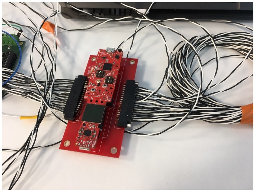
We are carrying all pins of IWR6843AOPEVM with its MPI-60pin hd connector. In this way, we can access all 60 pins of iwr6843aopevm board. And we can configure the board with UART over this connector. And we can read data from MSS_Logger pin.

We configure the board with SOP pins for flash mode, but we cannot program the flash. By the way, when we are working with setup, all pins that we are not using are floating.

If we program the IWR6843AOPEVM with onboard USB, we can configure and read data over 60 pin connector. And we are configure IWR6843AOPEVM as boost mode (like programming with MMWAVEICBOOST) to access the IWR6843AOPEVM over 60 pin connector. But we cannot program the flash over our connector setup.

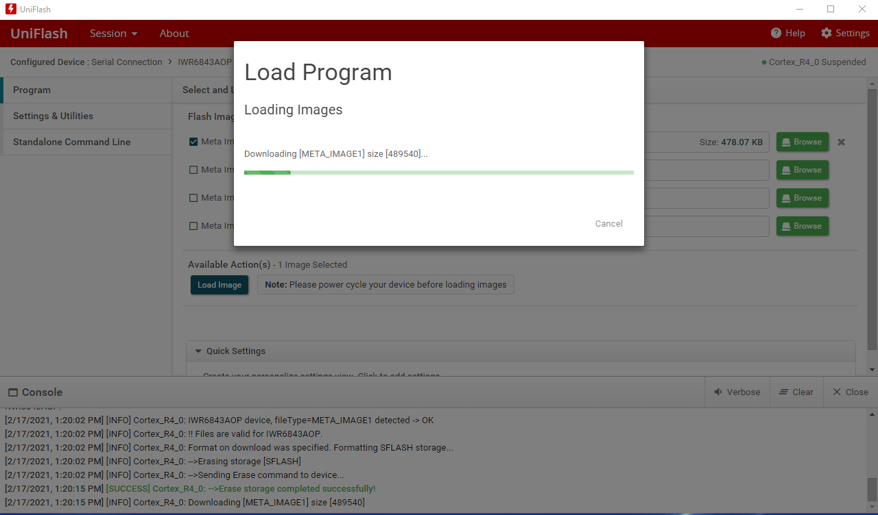
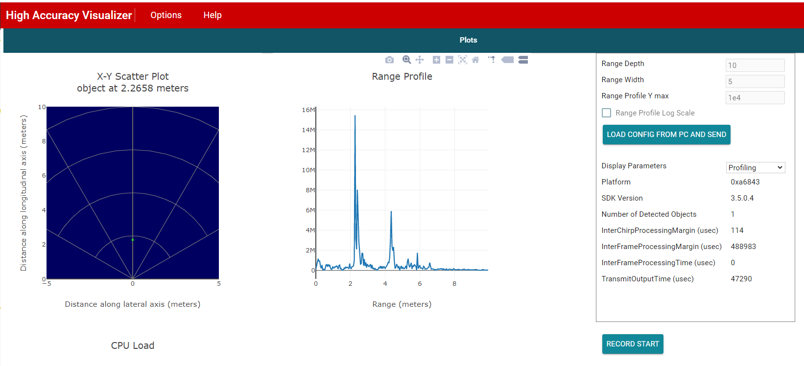
We are using uniflash for programming. And we use TI web based “High Accuracy Visualizer” tool to config and see receive data as visual.

There are screenshots from uniflash and High Accuracy Visualizer tool.

How can we write the program to flash of the IWR6843AOPEVM over its 60pin connector without MMWAVEICBOOST Which step do u think we are skipping?

  • Hello

    Seems like you are listing a quite a few things that you have attempted and hurdle on each one.

    To focus debug effort on right things can you please list the end objective  that you wish to accomplish

    1. Flash via which interface

    2. Collect data via which interface

    please list the board->interface -> pins  you wish to utilize for the above tasks.

    Thank you,

    Vaibhav

  • Hello

    If we summarize the things we want to do.

    • In IWR6843AOP_EVM, we want to program and run FLASH using the pins going to the 60 pin connector.
    • The pins we use for the 60pin made for this are as follows.

    1.  MSS_Logger( IWR6843AOP_EVM 60 pin header pin 18) ---- uart tx (converter to PC)
    2.  RS232_Tx    ( IWR6843AOP_EVM 60 pin header pin 57)  ---- converter rx (converter to PC)
    3.  RS232_Rx    ( IWR6843AOP_EVM 60 pin header pin 59)  ---- coverter tx (converter to PC)
    4. We set the SOP [2: 0] (( IWR6843AOP_EVM 60 pin header pin 17/24/49) )pins on the IWR6843_EVM and moved to the 60 pin connector to 101.
    5. Supply voltage. (5V - GND)

    If we sum up the problem. Using the above pins on the 60pin connector, we were MMWAVEICBOOST. But we couldn't succeed when we used the pins on the 60 pin connector directly.

  • Hi,

    For this you need to configure the IWR6843AOPEVM for MMWAVEICBOOST Mode, This should route the signals to the 60 pin header.

    You also need to configure the SOP Pin to flashing or functional mode. Since you dont have the ICBOOST connected you can configure the SOP using the IWR6843AOPEVM switches or pull those pins high on the adapter.

    You also need to confirm that the converter you are using is compatible with Unifilash.

    Regards,

    Charles O

  • Hi Charles thanks for reply.

    The corresponding pins on the IWR6843AOPEVM were directed to the 60 pin connector. I'm sure about this part. Because I can perform all my operations using MMWAVEICBOOST. The only problem is I cannot program when I physically move the relevant pin connections outside. Is there any other connection I should make other than the pin connections I made in my previous post? So;

    • MSS_LOGGER
    • RS232_RX
    • RS232_TX
    • SOP [2: 0]
    • Supply (5V-GND)

    Will it be enough to physically move the connections outside and make the connections? How can I confirm that the converter I am using is compatible with Unifilash?

  • Hi,

    Those are the pins you need for programming and flashing. Can you confirm oscope or logic analyser that you are getting data out on the adapter board?

    Can you also confirm how you are pulling the SOP line to the right voltage. You can set the SOP using the on board switches rather than the pins on the adapter board.

    Regards,

    Charles O

  • Hello again,

    I wanted to explain the subject from the beginning.

    We want to program the flash which is settled on IWR6843aopewm board. We want to write the code to this flash via UART pins, RS232_RX & RS232_TX (57 & 59 pins on connector). We can carrying these pins via 60 pin connector which already placed on IWR6843aopewm. And after that, we want to collect data over MSS_Logger pin of chip. And we can carrying this pin via 60 pin connector too. In this point, we can collecting data via this pin. It is ok. There is no problem in this step. But we cannot writing the code to flash.

    We want to write code to onboard flash. We’ve examined the schematic and PCB documents of IWR6843AOPEVM for “how it could write the code to flash”

    We see that, It carrying the RS232_RX & RS232_TX and MSS_Logger (18th pin of 60 connector) pins to the onboard USB via USB bridge. So we are trying to make this process via 60 pin connector. Because these pins already carried to this connector too.

    SOP Steps:

    When we are trying to program flash with 60 pin connector, we configure the IWR6843AOPEVM as IWRBoost module to access all pins from 60 pin connector.

    After that we’ve also tried pull-up and pull-down to SOP pins via 3.3V and beside that we’ve tried to configure NRESET and Warmreset pins like made on IWRBosst module.

    After all process, we want to learn “how can we program the QSPI flash on IWR6843AOPEVM, and we want to collect data via TI web based “High Accuracy Visualizer” tool. Because we want make our own board with this IWR6843AOP chip.

    I think we are making everything right, but there should be another step we are skipping.

    Thanks in advance

  • Hi,

    I wanted to make sure you are aware that you can flash and run demos on the xWR6843AOPEVM without needing the MMWAVEICBOOST or the adapter you have made. 

    https://training.ti.com/hardware-setup-iwr6843aop

    https://dev.ti.com/tirex/explore/node?node=AIHy77joqu3jXFmjqwkBKQ__VLyFKFf__LATEST

    To program and run the demo on your adapter board you need to

    1. Configure the AOP EVM for MMWAVEICBOOST Mode 
    2. Interface the adapter with a USB to UART converter, something like the XDS110 debug probe.
    3. Configure the SOP to the right mode mode, pulling up or down the SOP pins as needed
    4. Connect to the right COM port on uniflash and flash the demo binary. This programs the  QSPI FLASH
    5. set SOP mode back to functional mode
    6. Connect both user and data com port to demo visualizer and run it.

    I hope this answers the question

  • Hi, thanks for your answer,

    Unfortunately, it is not solve our problem.

    As I said before, we've already applied these steps. But we could not program to QSPI flash. 

    But there is one thing. We don't use XDS110, we are using another USRT-USB transceiver. Is there can be a problem in this point? Or is there another pins except UART and SOP pins we should check? For example we have tried to pull-up and pull-down to NRST, Warmreset, Nerr-in pins. And another example; in mmwaveboost board, different pins enter to XDS110 too. 

    And can you direct us to someone who interested IWR6843AOPEVM board design? Because, at the and of all these steps, we want to use IWR6843AOP on our own designs.

    Thanks again.

  • Hi,

    If the EVM is working in standalone mode and with MMWAVEICBOOST then your setup, at a glance, should work with the steps in my previous post.

    1. I looked back at the image you share and first of all the cables attached to the adapter board appears to be really long, at higher speed this could affect signal integrity.
    2. Secondly, you need to confirm that he UART to USB transceiver you are using actually works with uniflash and the visualizer. Have you successfully used this to program and run demos in the past?
    3. When using the adapter how is the board powered? 
    4. Can you configure the SOP pin on the AOP EVM and power using onboard USB. Instead of having all the 60 pin connected to the cables. route only the ground, UART RX, UART TX, and mss_logger to the the USB to UART. 

    Can you please provide any additional details that you think is applicable?

    Regards,

    Charles O

  • Hi,

    First of all, it was worked with MMWAVEICBOOST. And we collect data with our setup without MMWAVEICBOOST.

    Answers:

    1-) I have prepare a new setup with just RX, TX, MSS_LOGGER, and GND pins, and cable length are approximately 8-10cm. 

    2-) As I said before, we have configure and collect data from MSS_LOGGER pin with our setup, so we can say that our transceiver is worked. But in this point you are talking about second time uniflash compatibility. How can we verify its compatibility?

    3-) We have power it from 60pin connector. But today we have just powered it from second settled USB connector.

    4-) Yes I have tried all configuration probabilities. I have tried as MMWAVEICBOOST mode and pull-up SOPs with external 3.3V(GNDs are same). And I tried configure SOPs on IWR6843AOPEVM. No-one is worked.

    Now, we should ask that, in schematic document of PROC091F (IWR6843AOPEVM) there are some conflicting information. For example, one table said "Flash mode is 001, the other one said 101 " Of course we have tried all probabilities but there are some differences. 

    And I ask that, can we use RX-TX-MSS_LOGGER pins without configure IWR6843AOPEVM as MMWAVEICBOOST mode. (By the way, we have tried both way)

    And another question is, in schematic document of PROC091F (IWR6843AOPEVM), there are pin mux settings table. And this table is said S1.2 is ON for 60pin UART. (By the way, we have tried this one too.)

    At the end of the my questions, we think that, there should be another step like connection, pull-up/down or something like that. We are not wrong, probably missing 1-2 so simple steps. But we could not find it yet. Because of that, we are asking that can you direct us someone who interested design of IWR6843AOPEVM board or IWR6843AOP MCU. 

    Thanks in advance...

  • Hello,

        Device wakeup procedure we need to follow as shown in the below timing specified in the datasheet. 

    Few points to emphasize here are:

    1) Power supply need to be applied and stable 

    2) SOP boot mode assertion need to happen before the NReset release : This captures should the device be in Functional mode or fleshing mode.

    3) Then device would be ready for appropriate mode. If it's flashing mode, then device would expect flash image on RS232  TX/RX pins which are connected to  USB to UART port. 


    While Device is connected to USB to UART port, Care need to be taken non-fail safe I/Os such as RS232 Tx/Rx signal should not be driven when the VIO supply is not present.

    Hence, it recommended all the external connection to mmWave IC should be disconnected when the VIO supply is not present. Power up the device with right boot configuration, and then connect external interfaces such as USB to UART ports. 

    Thanks and regards,

    CHETHAN KUMAR Y.B.