This thread has been locked.

If you have a related question, please click the "Ask a related question" button in the top right corner. The newly created question will be automatically linked to this question.

FDC1004: Different capacitance value measured when CAPDAC change

Part Number: FDC1004


Hello,

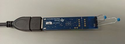
I am working for develop a system of measuring capacitance by FDC1004. The system is contain a FDC and a microcontroller thru I2C simply. My question is a consistency of CAPDAC. 

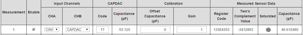
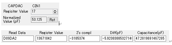
In this case, the measurement target is having the fixed capacitance near around 50pF like this. 

 (Diff is the difference from CAPDAC zero. acquiring software is my own making.)

But that capacitance is suddenly moving when I change the CAPDAC.

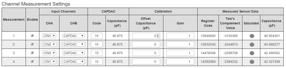
No such the phenomenon is occurring at the other range of CAPDAC and the capacitance of measurement target. This is near around 50pF. 

I read some of other posts but this case is not only restricted the capacitance range but also difference of capacitance is huge. Let me know your opinion.

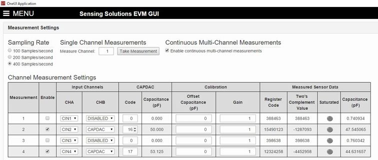
Other setting of registers are RATE=100S/s, no offset calibration and no gain calibration.

Thanks,

KOH

  • Koh,

    Thank you for your inquiry and your interest in TI products.

    Without more knowledge of your set-up, it is hard to offer a solution, but I do have a few questions:

    1. What is the equation to get the parameter Diff(pF)?

    2. What is the equation for Capacitance (pF)?

    3. How do you calculate the number in the 2's complement field?

    4. What are the settings the Measurement Configuration Registers, as shown in Table 4 of the data sheet? 

  • John,
    Thank you for your reply. Please refer below.

    1. What is the equation to get the parameter Diff(pF)?
    Coffset:(CAPDAC register setting)16(=b10000) * (resolution)3.125pF = 50.00pF
    Diff(pF):(Actual measurement capacitance)50.9522....pF - (Coffset) 50pF ≠ 0.9522.....pF

    Coffset:(CAPDAC register setting)17(=b10001) * (resolution)3.125pF = (CAPDAC) 53.125pF
    Diff(pF):(Actual measurement capacitance)47.2019....pF - (Coffset) 53.125pF ≠ -5.9230.....pF

    2. What is the equation for Capacitance (pF)?
    Measured number(as C) is positive : C / 2^19 + Coffset
    Measured number(as C) is negative : 2's complement of C / 2^19 + Coffset

    3. How do you calculate the number in the 2's complement field?
    (Measurement[23:0]) XOR (0xFFFFFF) + 1

    4. What are the settings the Measurement Configuration Registers, as shown in Table 4 of the data sheet?
    0x08 CONF_MEAS1 = 0x1200(CAPDAC 16) or 0x1220(CAPDAC 17)

    I also have EVM and the behavior of the time of CAPDAC 16 and 17 against the measurement target around 50pF is same. I used my own developing system to report this issue at first because EVM and software is sometimes buggy.

    Regards,
    KOH

  • KOH,

    Thank you for the extra information.

    I will try to reproduce your findings and provide an update by the end of this week.

  • KOH,

    I had planned to use my EVM to reproduce what you have seen.

    Unfortunately my EVM is bad, and I have had to order another one, which I probably won't get until the end of this week.

    So it is unlikely I will have an update by Friday. An update by Wednesday of next week is more likely.

    Apologies for the delay.

  • KOH,

    One of my colleagues was supporting an E2E inquiry that seems similar to yours, and she found a previous thread that may help with your questions.

    Please review e2e.ti.com/.../845925 and let me know if it resolves your question, or if you have any more questions.

  • John,

    I already referred that article. It is acceptable that the small number of difference between every each CAPDAC step but this problem is not quite same as that step accuracy because this difference is too big and this problem is happening on the restricted steps of CAPDAC (around 4pF diff between 16 and 17, sometimes around 4pF between 17 and 18, and I found new case around 2pF between 25 and 26 - I can't grasp the definition of the condition of CAPDAC around 16 to 18). I have to clear the characteristics even if I can add the fixed offset for restricted range. Do you have any assistance?

    One thing that I could get a new point of view from that article is that "using the offset set to -16pf". I will try this.

    Regards,

    KOH

  • KOH,

    I just received a notice that my EVMs just shipped from the TI store and that it will take 3-5 business days before I receive them, probably in the last few days of next week. Once they are in-hand I will try to reproduce what you have seen. 

    Please let me knw how it goes with the new offset setting.

  • John,

    Thank you for your preparing to test.
    I confirmed that the offset setting would not affect for this phenomenon. It seems that there is no other way of fixing CAPDAC around those points where is different capacitance measured by changing CAPDAC. It is OK if I wanted to measure the area of ±16 pF anywhere in 100 pF but it means that FDC could not sense monotonous transition of caps throughout 100 pF.

    I checked again the setting of CAPDAC around 16 to 18 for several FDC1004s that I have. The happening cases of "16 and 17" and "17 and 18" are depends on the individual chip. I think this IC is switching internal capacitors consecutively and I also think that the boundary and accuracy of switching is different in every individual ICs. It will be the huge help that I could know the certain characteristic if my thought is right. I found the case of 16~18 and 25~26 but I don't know other point is existing or not (when internal capacitors switch?). Maybe I can try to avoid those area of capacitance (or compensate by software...).

    Regards,

    KOH

  • KOH,

    I received my EVMs yesterday. I am in the middle of  another high-priority project and will start my testing on Thursday.

  • KOH,

    I received an EVM and have not been able to reproduce what your results.

    Are your results  based on a TI EVM, or your own PCB?

  • John,

    I tried both cases as you can see the pictures in my latest posts. My PCB is driven by my GUI (thru serial communication from Windows to μC, I2C from μC to FDC). EVM is also driven by Sensing Solution EVM GUI. I don't know the transmission architecture of EVM so I don't connect EVM GUI and my PCB so there is no affection to EVM if I am failing developing my design. I connected fixed or trimmable capacitor to CIN instead of electrode for both environment. 

    47pF capacitors for CIN2 and CIN4.

    Confirming difference by CAPDAC. EVM GUI is unstable.

    Regards,

    KOH

  • Keigo,

    Thank you for the additional information on what you have found.

    I will try to reproduce your findings in the lab on Monday, and will update this thread no later than Wednesday.

  • Keigo,

    I modified an EVM by adding 47pF caps from C1 - C4 to ground.

    Then I tried stepping the CAPDAC values from 14 to 17 for all four of the channels. The measured capacitance was close for all four capacitors, and the measured values did show much variation over the CAPDAC changes. See the images below.

    When I tried changing the CAPDAC values across the four channels in a single measurement, the results changed, especially for C2, with a CAPDAC code of 15 (46.875pF). 

    So it looks like if the CAPDAC values are the same across the four channels, the results are consistent, but if they vary across the four channels, the results start to vary. 

    This seems to be consistent with what you have found. I will investigate this further and will re-open & update the thread when there are results to share. 

    Thank you for sharing your findings with us. 

  • John,

    Thank you for your detailed investigation. I've never tried for all channels at one time.

    I am looking forward to further investigation of this problem and update.

    Regards,
    KOH

  • Keigo,

    I spoke with other members of our team about our findings on the FDC1004.
    A single CAPDAC setting applies to all of the channels in the FDC1004.
    There is no dedicated CAPDAC setting for each channel, the single setting is applied across all four channels for non-differential measurements.

    Our Sensing GUI does not make this clear. 
    It seems to allow a user to make a distinct CAPDAC setting for each channel, but it is really changing the single CAPDAC setting as it multiplexes between the channels. From what we saw in our experiments, this GUI approach seems to be a little unreliable.

    I hope this helps. Please let me know if you have any more questions. 

  • John,

    This problem that I confirmed was happened not only at the time of using FDC1004 by single channel but also not on the EVM GUI at first. 

    I am concerning to use only one channel for my latest development. Sure I posted the picture of multiple channels measurement on 12th article, but that was intended to make this phenomenon easier to understand. The pictures on the 3rd post of this article is showing only CIN1, but the CAPDAC of other channels were "DISABLED" in the out of pictures at this case. 

    I measured and captured the pictures again but I could not find the way of upload. Didn't find this phenomenon on your environment? Please try CAPDAC settings 16~18 for one Ch for one target of capacitance.

    I need to know the certain characteristics of CAPDAC to avoid or to compensate this big error. It is good if there's a way of prevent. Small errors by every steps are acceptable but these big errors are seemed to happen on the restricted steps/capacitance area. I mean characteristics are regarding this problem. Certain settings of CAPDAC steps to happen, margin of error, there are individual difference for every chip or not, and/or so. Is it impossible?

    Regards,

    KOH 

  • Hello KOH,

    John will be out of the office until Tuesday. Alternatively, you can adjust the offset registers to account for any possible measurement errors introduced by the CAPDAC.

    Best regards,

    Nicole

  • Keigo,

    I will experiment with the CAPDAC = 16-18 settings as you suggested and update this thread tomorrow.

    The TI E2E has been upgraded, and some of the menus have changed. Apologies for any inconvenience.

    You can upload images and other files by first selecting the Insert/Image/video/file menu at the bottom of the window, then clicking Upload under the File/URL field on the resulting pop-up.

    Regards,
    John

  • Keigo,

    Using the TI/Sensing EVM GUI, I tried varying the CAPDAC code from 10 to 20 for channels 1 & 2 in separate measurements, and noting the reported capacitance.
    Both channels have 47pF caps in place of the EVM sensor.
    The data:

    CAPDAC Code CAPDAC Capacitance (pF) CIN1 (pF) CIN2 (pF)
    10 31.25 40.45 42.22
    11 34.375 40.52 42.29
    12 37.5 40.51 42.28
    13 40.625 40.57 42.34
    14 43.75 40.7 42.45
    15 46.875 40.67 42.43
    16 50 40.63 42.38
    17 53.125 40.75 42.51
    18 56.25 40.25 41.93
    19 59.375 43.375 43.375
    20 62.5 46.5 46.5

    When doing the measurements, I noticed for CAPDAC codes from 10-18, CIN1 and CIN2 varied slightly over time.
    For CAPDAC codes 19 & 20, CIN1 and CIN2 did not vary at all over time, and their values increased compared to CAPDAC settings 10-18.
    If we can believe the estimated values for CIN1 and CIN2 for CAPDAC = 10, then for for CAPDAC >18, the difference between the CAPDAC capacitance and the actual (sensor) capacitance is > 15pF.
    The FDC1004 has a range of ±15pF, so it is likely the sudden jump in CIN1/CIN2 capacitance (for CAPDAC > 18pF) is because the attempted measurement exceeds the range of the device.
    That may be what you are seeing. 

    Regards,
    John