This thread has been locked.

If you have a related question, please click the "Ask a related question" button in the top right corner. The newly created question will be automatically linked to this question.

AWR1843BOOST: DataCapturedemo_xWR.lua configuration file

Part Number: AWR1843BOOST
Other Parts Discussed in Thread: AWR1843, DCA1000EVM

Hello,

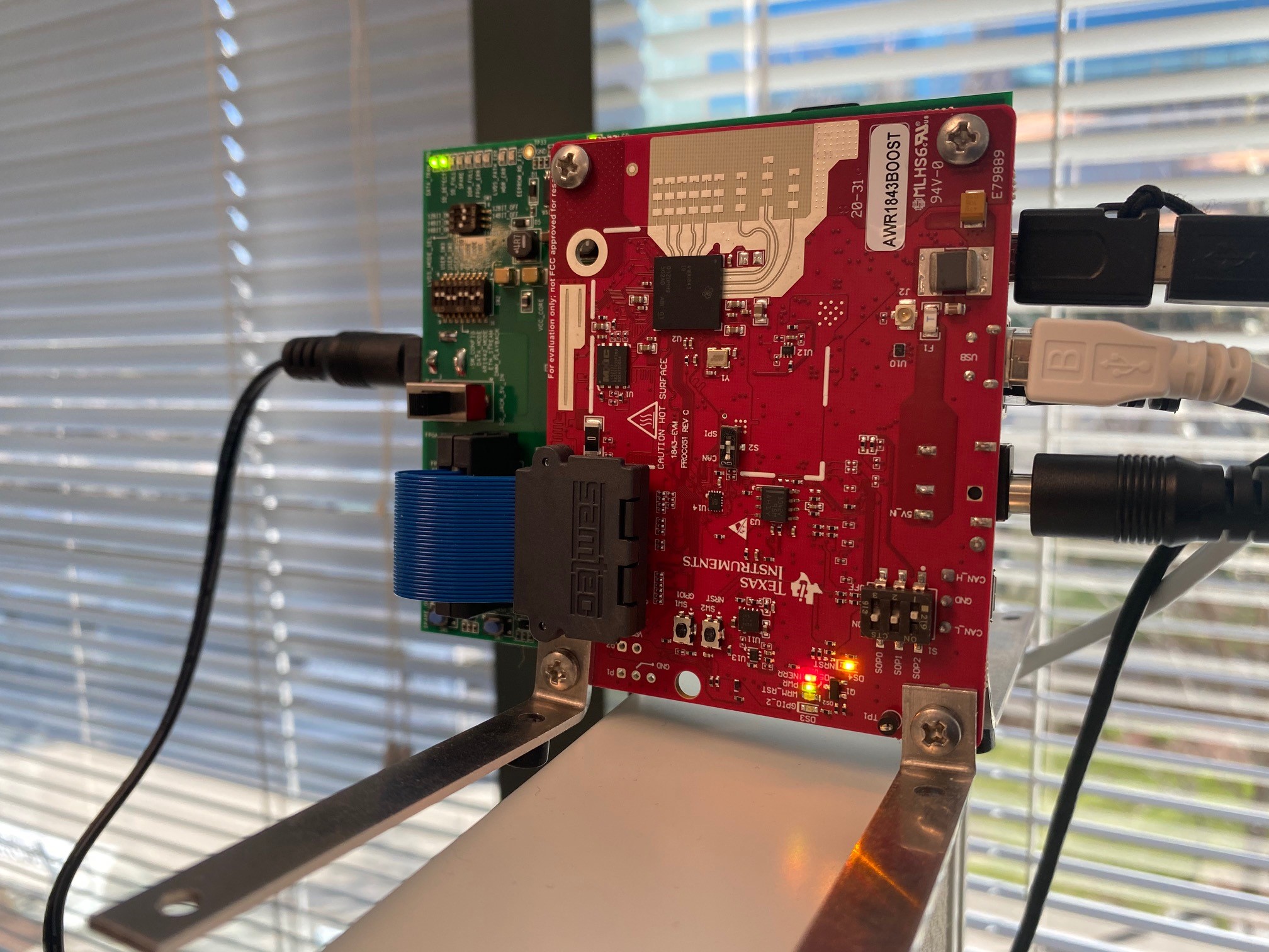
I am trying to use the AWR1843BOOST board with the DCA1000 capture board. following the quick start guide document (SPRUIK7–May 2018) and loading DataCapturedemo_xWR.lua config file, the system goes through and generates the .bin file and Matlab display, however, the display is always showing a target at 5 meters and does not change at all. Is there a better demo config file to use for evaluating the AWR1843 and DCA1000 demo combination?
Thanks,
Saied 
  • Hi,

    What environment would you like to evaluate the AWR1843 in?

    Are you interested in a longer range?

    The chirp configuration may have to be updated.

    thank you

    Cesar

  • Hi Cesar,

    Thanks for the quick response. I'm running the mmWave Studio app on a windows machine. At this point, all I want to do is to get the sensor to come up and perform basic functions. I'm able to run the sensor board alone using the mmWave Visualizer, so I know the HW is working. The issue I'm having is with raw adc captures using the DCA1000 board. The .bin file is generated but the data does not look right.

    Thanks for your help.

    Saied

  • Saied,

    In the DataCaptureDemo_xWR.lua file, please comment out or remove any commands that include "testsource". There should be two commands that include this string. These commands are enabling the test source feature of mmWave Studio, which overrides the ADC data received by the sensor. After you remove these lines, you should run the LUA script again and see if the results look more like the observed scene in which the radar sensor is placed.

    Regards,
    Kyle

  • Hi Kyle,

    Sorry for the simple question, but when I save the updated script, I keep getting an error that the file cannot be found!

    [14:03:45]  &&&&&&&&&&&&&&&&&&&&
    [14:03:45]  ***Script FAILED!***
    [14:03:45]  &&&&&&&&&&&&&&&&&&&&
    [14:03:45]  Exception message is:
    [14:03:45]  cannot open C:\ti\mmwave_studio_02_01_01_00\mmWaveStudio\Scripts\DataCaptureDemo_xWR_2.lua\bitoperations.lua: No such file or directory

    Even if I copy the original LUA file without edits, I get the same message - any ideas?

    Thanks,

    Saied

  • OK, I just re-saved the modified script with the same name and i'm able to load and run. however, now I get the message that no points are detected in the PostProc window. Here is a copy of the output messages:

    [14:41:12]  RfInit Success
    [14:41:13]  [RadarAPI]: ar1.DataPathConfig(1, 1, 0)
    [14:41:13]  [RadarAPI]: Status: Passed
    [14:41:13]  DataPathConfig Success
    [14:41:13]  [RadarAPI]: ar1.LvdsClkConfig(1, 1)
    [14:41:13]  [RadarAPI]: Status: Passed
    [14:41:13]  LvdsClkConfig Success
    [14:41:13]  [RadarAPI]: ar1.LVDSLaneConfig(0, 1, 1, 0, 0, 1, 0, 0)
    [14:41:13]  [RadarAPI]: Status: Passed
    [14:41:13]  LVDSLaneConfig Success
    [14:41:13]  [RadarAPI]: ar1.ProfileConfig(0, 77, 100, 6, 60, 0, 0, 0, 0, 0, 0, 29.982, 0, 256, 5000, 0, 0, 30)
    [14:41:13]  [RadarAPI]: Status: Passed
    [14:41:13]  ProfileConfig Success
    [14:41:14]  [RadarAPI]: ar1.ChirpConfig(0, 0, 0, 0, 0, 0, 0, 1, 1, 0)
    [14:41:14]  [RadarAPI]: Status: Passed
    [14:41:14]  ChirpConfig Success
    [14:41:14]  Test Source Already Disabled...!!!
    [14:41:14]  [RadarAPI]: ar1.DisableTestSource(0)
    [14:41:14]  [RadarAPI]: Status: Passed
    [14:41:14]  [RadarAPI]: ar1.FrameConfig(0, 0, 8, 128, 40, 0, 0, 1)
    [14:41:14]  [RadarAPI]: Status: Passed
    [14:41:14]  FrameConfig Success
    [14:41:14]  [RadarAPI]: ar1.SelectCaptureDevice("DCA1000")
    [14:41:14]  [RadarAPI]: Status: Passed
    [14:41:14]  SelectCaptureDevice Success
    [14:41:14]  [RadarAPI]: ar1.CaptureCardConfig_EthInit("192.168.33.30", "192.168.33.180", "c:22:38:4e:5a:c", 4096, 4098)
    [14:41:14]  [RadarAPI]: Sending fpga command to DCA1000
    [14:41:14]  [RadarAPI]:
    [14:41:14]  FPGA Configuration command : Success
    [14:41:14]  [RadarAPI]: Sending fpga_version command to DCA1000
    [14:41:14]  [RadarAPI]:
    [14:41:14]  
    [14:41:14]  FPGA Version : 2.8 [Record]
    [14:41:14]  
    [14:41:14]  CaptureCardConfig_EthInit Success
    [14:41:14]  [RadarAPI]: ar1.CaptureCardConfig_Mode(1, 2, 1, 2, 3, 0)
    [14:41:14]  [RadarAPI]: Sending fpga command to DCA1000
    [14:41:14]  [RadarAPI]:
    [14:41:14]  FPGA Configuration command : Success
    [14:41:14]  CaptureCardConfig_Mode Success
    [14:41:14]  [RadarAPI]: ar1.CaptureCardConfig_PacketDelay(25)
    [14:41:14]  [RadarAPI]: Sending fpga command to DCA1000
    [14:41:14]  [RadarAPI]:
    [14:41:14]  FPGA Configuration command : Success
    [14:41:14]  [RadarAPI]: Sending record command to DCA1000
    [14:41:14]  [RadarAPI]:
    [14:41:14]  Configure Record command : Success
    [14:41:14]  CaptureCardConfig_PacketDelay Success
    [14:41:14]  [RadarAPI]: ar1.CaptureCardConfig_StartRecord("C:\\ti\\mmwave_studio_02_01_01_00\\mmWaveStudio\\Scripts\\..\\PostProc\\adc_data.bin", 1)

    Thanks,

    Saied

  • Hello,

    We really need support on bringing up basic functionality on the AWR1843. We plan to use the chip in our upcoming prototype build and cannot proceed if we don't make any progress. We followed the mmWave Studio user guide step by step but still can't get meaningful captures. Is there an update for the user guide that includes AWR1843 settings in detail? The eval board is slightly different than what is shown in the documentation (dip switches for SOP).

    Please help!

    Thanks,

    NPS team

  • Saied,

    The change in the DIP switches for the SOP modes does not have an overall impact on the EVM. This was just a change from jumpers to DIP switches. When using the DCA1000EVM and the AWR1843BOOST, both SOP0 and SOP1 need to be set to the ON position while SOP2 needs to be set to the OFF position. The steps detailed in the Quick Start Guide are still applicable and the change from jumpers to DIP switches does not have an impact on the steps that need to be taken.

    Please provide pictures of your physical setup to help assist in debug.

    Regards,
    Kyle

  • Hi Kyle,

    I am finally able to capture the binary file but not consistently. The issues I'm running into are:

    1- I get the message "No LVDS data" about 1/3 of the time when I issue trigger frame command. The system is unresponsive for a while and then it comes back.

    2- Changing packet delay time in the RF capture card does not seem to take effect. It always reads back 25us.

    3- Red LED on RF card is on most of the time. Sometimes it turns off after FW download and SPI connect, but it's on most of the time.

    Here is a picture of the setup.

    Thanks for your help.

    Saied

  • Saied,

    I would suggest changing out the USB cable that you have connected to the DCA1000EVM. Try to use a micro-USB cable and not one that doubles as both a mini-USB and micro-USB.

    Regards,
    Kyle