This thread has been locked.

If you have a related question, please click the "Ask a related question" button in the top right corner. The newly created question will be automatically linked to this question.

AWR1642BOOST: AWR1642 BOOST

Part Number: AWR1642BOOST
Other Parts Discussed in Thread: AWR1642

Hi,

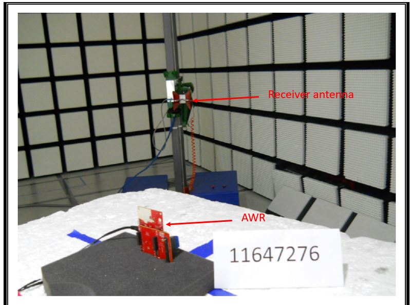
We have designed a PCB based on your reference design of RFCMOS77GHz. I need know , 

1) How can i measure the Radiating field strength and antenna patter measurement?

I mean what is the procedure for such this antenna calibration?

BR

Sreenath

  • Hello Sreenath,

    For measuring the antenna pattern you need to have an anachoic chamber setup with calibrations receiver antenna connected to a spectrum analyzer. You also need a mechanical system to rotate the board across different angles to measure the gain at different angles.

    Regards,

    vivek 

  • Hi,

    How can i connect the receiving antenna section to the spectrum analyzer. Does this design(RFCMOS77GHz) has any provision to connect it to the spectrum analyzer?

    BR

    Sreenath

  • Hello Sreenath,

    I meant using a separate receiver antenna to receive the signal transmitted by AWR device. Below is an example setup.

    Regards,

    Vivek

  • Hi,

    So AWR device will be continuously transmitting signal and the receiving antenna will rceive the chirp and will be send to the spectrum analyzer right?

    How exactly do the setup work can you explain?

    Is it possible to get the radiation pattern of the antenna and the radiating field strength from this setup?

    What are all the equipment and setup required for this?

    Also what is the other PCB board that is connected to the AWR1642 device in the figure?

    BR

    Sreenath

  • Hello Sreenath,

    Some tutorials online should help you understand how antenna patterns are measured, these are very standard procedures. You can find one such white paper at the following link: http://www.ets-lindgren.com/sites/etsauthor/WhitePapers/APM.pdf

    regards,
    vivek

  • Hello,

    Can the AWR device be changed into only receiving mode. for calibration and also  i have seen a J2 port in the AWR1642 boost device what is it used for?

    BR

    Sreenath

  • Hello Sreenath,

    If you disable the TX in the chirp configuration then they would not be turned ON.

    J2 connector on the 1642BOOST EVM is to bring out some internal clocks our for debug, like the APLL divided clock, reference clock etc.

    Regards,

    Vivek