This thread has been locked.

If you have a related question, please click the "Ask a related question" button in the top right corner. The newly created question will be automatically linked to this question.

AWR2243: Extracting the ADC raw data from the CSI packet

Part Number: AWR2243

Hi,

I have 2 questions to get better understanding of the received data from MIPI CSI2 core in the purpose of applying further signal processing on those data.

Question 1: How is the raw ADC data mapped to the CSI packet going to the external host?

Here are the summery of the studies we have done regarding that:

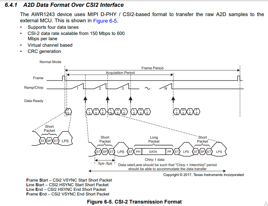
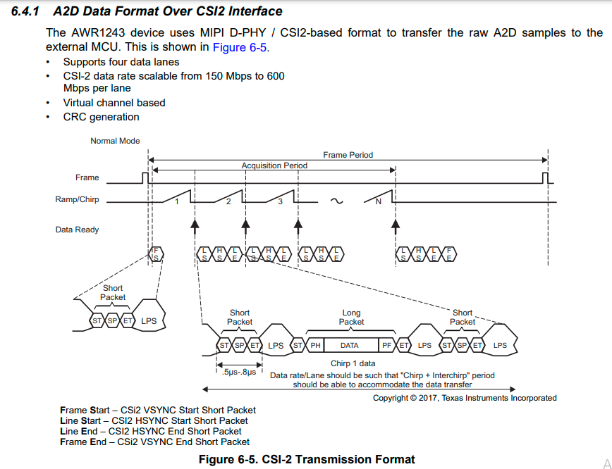
-          From the AWR2243 data sheet: the chirp sampled data are packetized in the following format including the frame start indicator at the beginning of the packet’s series.

  • In the above figure, I am assuming that each “Chirp 1 data” can contain CP and CQ depends on the “DATA_PATH_CONF”. Is that right?
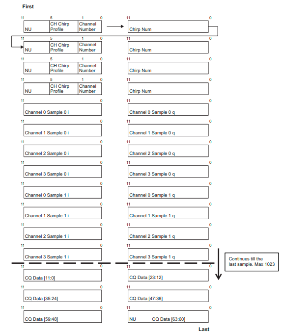
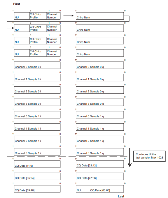
  • Following figure shows a sample of the data payload, Datasheet mentioned that “The payload is then split across the four physical data lanes and transmitted to the receiving D-PHY”. Does it mean that, each of the above transferring “chirp 1 data” over a specific lane contains the “ NU+CH chirp Profile+ChannelNumber+ChirpNumber+Channel0smaple0i+ Channel0smaple0q+ Channel0smaple1i+ Channel0smaple1q+ … Channel0smapleNi+ Channel0smapleNq+CQData” ???

  • I think the main question is, how that data payload is mapped to different lines of different lanes?

Question 2: What should we expect to get from the MIPI CSI2 IP as the data output for further processing?

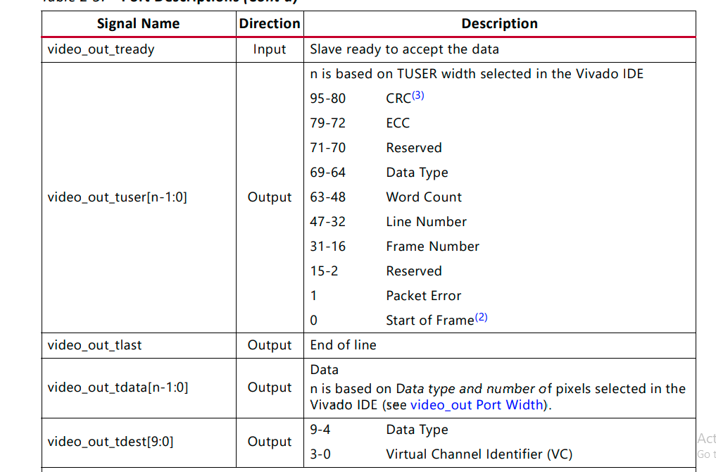
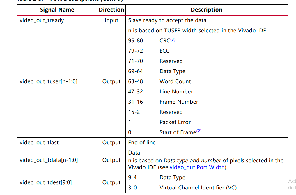
-          Does MIPI CSI2 core reconstruct the data payload as it is shown in above figure to deliver them to the output port?

-          From one of the related forums: “The ADC Config "Bits:16" is sent out of the device as RAW8 data. The RAW12 and RAW14 are "Bits:12" and "Bits:14" respectively”. Please confirm it.

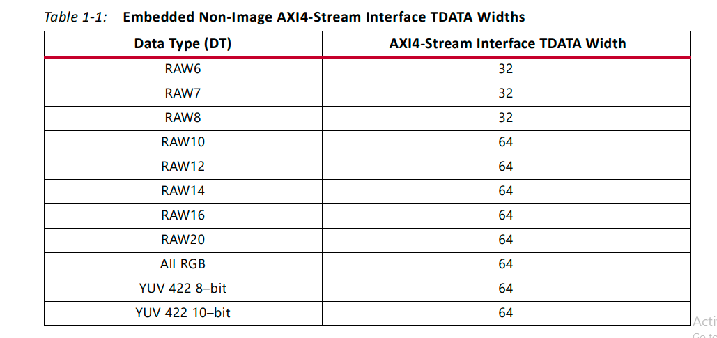
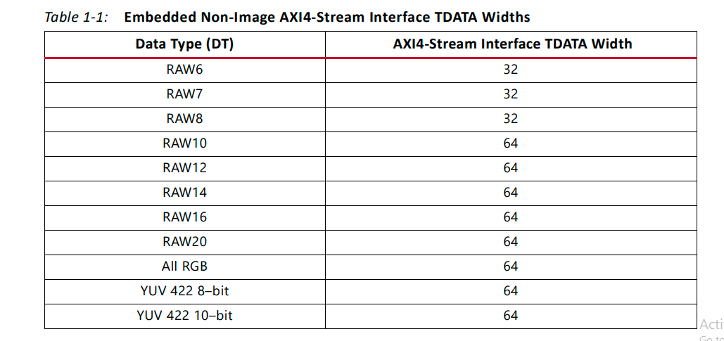
-          Considering the MIPI CSI2 RX IP datasheet, the TDATA width of RAW8 is 32. In the case of using 16 bits complex ADC data (Raw8), Does it mean the 16 bits “I” sample are assigned to the first 16 bits of the data output and the 16 bits “q” samples are assigned to the second 16 bits of the data output?

-          When/How should I expect to get CP and CQ info of that specific lines (if the ADC samples and CP/CQ data are packetized/mapped in one specific line (back to the first question))   

In the following figures, I have tried to represent two different ways of sequencing the data output. Would you please let me know which one can be possibly correct? Please let me know the proper representation of the data output if non of them is correct.

Thanks

Amin

  • Hi,

    I have 2 questions to get better understanding of the received data from MIPI CSI2 core in the purpose of applying further signal processing on those data.

    Question 1: How is the raw ADC data mapped to the CSI packet going to the external host?

    Here are the summery of the studies we have done regarding that:

    -          From the AWR2243 data sheet: the chirp sampled data are packetized in the following format including the frame start indicator at the beginning of the packet’s series.

    • In the above figure, I am assuming that each “Chirp 1 data” can contain CP and CQ depends on the “DATA_PATH_CONF”. Is that right?
    • Following figure shows a sample of the data payload, Datasheet mentioned that “The payload is then split across the four physical data lanes and transmitted to the receiving D-PHY”. Does it mean that, each of the above transferring “chirp 1 data” over a specific lane contains the “ NU+CH chirp Profile+ChannelNumber+ChirpNumber+Channel0smaple0i+ Channel0smaple0q+ Channel0smaple1i+ Channel0smaple1q+ … Channel0smapleNi+ Channel0smapleNq+CQData” ???

    • I think the main question is, how that data payload is mapped to different lines of different lanes?

    Question 2: What should we expect to get from the MIPI CSI2 IP as the data output for further processing?

    -          Does MIPI CSI2 core reconstruct the data payload as it is shown in above figure to deliver them to the output port?

    -          From one of the related forums: “The ADC Config "Bits:16" is sent out of the device as RAW8 data. The RAW12 and RAW14 are "Bits:12" and "Bits:14" respectively”. Please confirm it.

    -          Considering the MIPI CSI2 RX IP datasheet, the TDATA width of RAW8 is 32. In the case of using 16 bits complex ADC data (Raw8), Does it mean the 16 bits “I” sample are assigned to the first 16 bits of the data output and the 16 bits “q” samples are assigned to the second 16 bits of the data output?

    -          When/How should I expect to get CP and CQ info of that specific lines (if the ADC samples and CP/CQ data are packetized/mapped in one specific line (back to the first question))   

    In the following figures, I have tried to represent two different ways of sequencing the data output. Would you please let me know which one can be possibly correct? Please let me know the proper representation of the data output if non of them is correct.

    Thanks

    Amin
  • Hello Amin,

    TDA2x based Radar SDK implements this whole chain where it read ADC data from AWR device over CSI-2 chain and process it. You can refer that for more understanding.

    And these two documents explain the data format of ADC data over LVDS/CSI-2

    http://www.ti.com/lit/an/swra581b/swra581b.pdf

    http://www.ti.com/lit/an/swra555/swra555.pdf

    Regards,

    Jitendra