This thread has been locked.

If you have a related question, please click the "Ask a related question" button in the top right corner. The newly created question will be automatically linked to this question.

IWR6843: Reset and Interrupt signals

Part Number: IWR6843
Other Parts Discussed in Thread: DCA1000EVM, , , UNIFLASH

Good morning all,

I have been using the mmwaveLink layer with the IWR6843 revision D radar, with a customary 60pin (the one described in the schematics of this radar board - 60 pin-HD for DCA1000EVM). The aim is to mimic the mmwave Studio, which according to documentation, follows a mmwaveLink layer below.

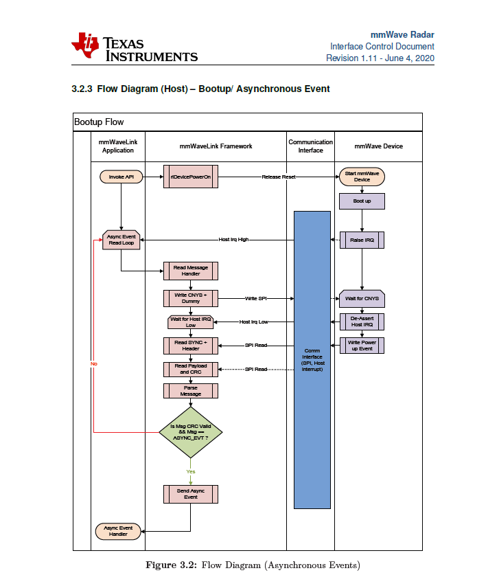
My problem is that when I send a reset - I active low the lane to the radar - I do not get any response from the Interrupt lane (as seen in the MMWave Radar Interface Control manual). I have atatched the communication protocol when booting up. Am I missing something? Do I need to have the firmware downloaded to receive an interrupt when it comes to the IWR6843?

 BR,

Gorka

  • Gorka,

          Yes, for this flow Firmware need to be loaded.  Trying to understand your problem, In IWR6843ISK board NRESET is applied by physically pressing a button. 

    Could you please elaborate more on  "when I send a reset - I active low the lane to the radar". If you could explain your setup details would help us to understand the system. How you are sending reset command? 

    Also please post pictures of setup and EVM for your configuration?

    Thanks and regards,

    CHETHAN KUMAR Y.B.

  • Hello Chethan,

    Yes, sure! The final aim is to directly use your 60GHz radar with an external host (FPGA), without using the DSP that is integrated within the radar package. This is, control, configure and trigger the radar(with SPI, Interrupt and RST lanes), and collect the data stream from LVDS lanes. As far as I know, there is no need of firmware download for the power up step of the radars, this is, bringing from idle the radar putting low the reset lane down with the command rlDevicePowerOn(.). Now, I will use the schematics of the IWR6843ISK revision D schematics, and how I understand it from there.

    The RADAR_NRST pin of the radar chip gets low, either from the external pin RADAR_NRST_1 or S2 switch, due to the logic combiantion of AND. So, when I set low the commented radar reset lane, I do not get any interrupt high from the RADAR_HOSTINTR1.  Also, my belief was that there was no need of loading the firmware to get the radar out of idle, as I think I remember from a mmwaveLink user guide documentation. Anyway, I also flashed too the FLASH, with a metaimage made with the firmware used on mmwave Studio, and it did not work either. I used this link, I asked several months ago https://e2e.ti.com/support/sensors/f/sensors-forum/880193/iwr6843isk-full-communication-control-configuration-of-the-radar-with-fpga/3261973#3261973 . Let me know what it is not properlz done.

    BR,

    Gorka

  • Gorka,

        Thanks for providing additional details, After ROM boot loader you have to load the MSS and BSS firmware image. Only after loading these images you would be able to send API commands. 

    At high level mmWave studio and DCA1000 (FPGA based capture card)  EVM training video's you could see from the below link. 

    https://training.ti.com/dca1000-training-video 

    To get host interrupt, you need to have MSS application and IWR6843 corresponding BSS image should be loaded into device memory, after SPI connection, host should be able to issue mmWave link layer API commands. 

    Thanks and regards,

    CHETHAN KUMAR Y.B.

  • Hello Chethan,

    I am not sure what to follow then, since according to the Application Report SWRA627 – October 2018 IWR6843 Bootloader Flow, there is a possibility shown in the figure 4 expressing that it is possible that the flash is not present, and so directly an IRQ is sent from the radar. I have attached the diagram. Please, could you let me know what it is wrong or what it is the way to follow? I will try again loading the firmware and waiting for the interrupt as the other way we commented, and also shown in the commented diagram. 

    I think, I might be missing some point somewhere in another document, or some important step. Thank you!

    BR,

    Gorka

  • Hello

    Before we get into the software modification side of things (ie. using mmWvae link calls  from  cortex R4f/DSP   to the RF Front end managed by RadarSS  )  wanted to make sure your Hardware is compatible with images that are already provided for using the Raw Data capture solution.

    In order to confirm lets  go through following successive steps:

    1. Is board working:

    Is device booting, able to load image from flash, run it,  result of OOB demo.

    This will ensure that the board functional

    2. Is the board studio compatible: (Considering the intent is to get studio equivalent setup working)

    Is it possible to  boot the image is the Studio suggested mode and load the  provided binaries (steps listed in DCA1000 flow)

    Before we proceed to #2 we should get #1 working.

    If #2 is the only part not working we may have multiple debug/resolution routes.

    Please help us know the results for #1 and #2.

    Thank you,

    Vaibhav

  • Hello Vaibhav,

    Point number one looks working for me, since I decided to try again loading the Flash, after creating again a metaimage with the firmware binary files from mmwave Studio.

    I was able to bring from idle and record with my HW setup and the IWR6843 plus mmwave Studio platform. Then, I moved to the implementation of mmwavelink layer within the example of the nonOs application. Now, I also see the response of the radar after the reset, meaning that I got an IRQ high, as I was expecting and thus I would say the essence of the question I posted is solved. I thought that without firmware the radar would be able to communicate with the external host, as the posted diagram from user guide IWR6843 Bootloader, but looks like something is not okay for that specific case.

    Anyway, I move from no firmware approach to a re-compiled flashed firmware approach, and it looks it worked. I have now several issues with the nonOS application, mostly with what specific function each of the rls_studio do when using nonOS environment. If you have a thourough user guide, better than the one explaining the porting within the DFP pack, I would like to get it, so I know which are the exact features of each functions under nonOS app, such as clientCtx.devCtrlCb.rlDeviceWaitIrqStatus = rlsDeviceWaitIrqStatus or any inside the powerOnMaster function in the nonOs mmw_example_nonOS.c app.

    BR,

    Gorka

  • Hello

    For #1) Good to know that flashing, loading, run mechanism is checkedout to be working. I am not sure why the mmWavestudio image was used to check this but we will move on considering the intent of #1 is achieved.

    #2) For Replicating the Studio functionality:

    1.  Do you have the required FTDI compatible device on board which mmWave Studio recognizes
    2. Is your intent to the use the mmWave Studio to load the images on to the device
    3. Please confirm ithat mmwave studio is able to communicate with the device/board and carryout the studio functionality.

    Wanted to flush the Steps in #2 using the images provided by TI for mmWave studio eco system before getting into any Software Modification.

    Thank you,

    Vaibhav

  • Hello,

    Let me explain everything in one comment, since I attached the  https://e2e.ti.com/support/sensors/f/sensors-forum/880193/iwr6843isk-full-communication-control-configuration-of-the-radar-with-fpga/3261973#3261973 question that I asked several months ago, and I am not sure if you followed all the chain. The goal is to build my own IWR6843 radar with the dedicated 60pin hd that originally is connected to the DCA1000evm to a new connection with a FPGA board. The final goal, then, is to control, configure and process all the data that comes from the IWR6843 radar on an FPGA, instead of PC or DSP.

    Now, I wanted to use the Mmwave Studio firmware since it is, up to some point too, more handable that the CCS code that running the source code for the whole DPSs implementation (note here that I also find, from my point of view, quite a bit extent the mmwaveLink layer/driver - for the purpose of setting up some registers). This way, I just configured and control the radar registers, so I do not need to take care of the signal processing afterwards (and related src).

    Therefore, answering to your points, 

    1.- I do not use FTDI, since I directly connect SPI, Interrupt and Reset to the FPGA, as well as, LVDS for ADC data streaming.

    2.- No, I use Uniflash to flash the radar with the executable attached in the link above to create the metaimages.

    3.- The Mmwave Studio works and records with my obtained metaimage, being able to carry out all the commands.

    Anyway, my first or original question was about why the documentation says something that does not happen, or at least, I did not see in my setup when powering up the radar and putting the reset active low. I did not get any interrupt from the radar without having downloaded the firmware, which collides with the documentation and mmwave Studio 8also with the fact that we can power up the radar without having any firmware when using the Mmwave Studio. As far as I understood, from the diagram, and from the Mmwave Firmware download app command, the firmware could well be downloaded after powering up and bringing from idle the radar MSS. At the end, I decided to take the other path (also shown in the diagram) and download the mentioned metaimage, and start from there, and it looks the radar responds correctly.

    BR, 

    Gorka

  • Hello

    A quick question

    Are you expecting the IRQ   for the 'no flash' present case for the bootloader flow.  This is prior to image load from flash.

    or

    Is the expectation for the interrupt after the image load from flash.  For this we would have to go into protocol  interaction  similar to what occurs after the   MSS/BSS load.

    Thank you for the details. That definitely helps, I do have more questions and will get back to you.

    Vaibhav

  • Hello,

    So I was firstly expecting IRQ high before firmware download, but since I could not see anything, I decided to take the second path in the bootup diagram, and load the metaimage directly. Then, I saw the IRQ high when setting Reset active low. My main question was, why without firmware I was not able to see the this event happening. I think the protocol for bootup, for either firmware/non firmware cases, should be the same, according to the mmwavelink diagram also attached above, since I assumed there was some kind of preloaded image in the radar, even when there is no firmware downloaded (either from debug mode, or flash mode). 

    BR, Gorka

  • Hello

    Out of the two scenarios I was asking, the 1st IRQ was for case where flash is not found. So that won't be applicable in your case.

    For 2nd case the interaction would be  after image is loaded from flash after bootup and expected IRQ is  part of the Host and mmWave device handshake. Would you say this 2nd case would apply to you.

    2nd scenario snapshot:

    Considering the debug is needed for 2nd scenario:

    1. If you flash the same image on TI's EVM is the required IRQ seen.

    2. Is host able to send the command to the device

    Please do check your private messages on this forum.

    Thank you,

    Vaibhav

  • Hello,

    My original question was actually related to non flashed firmware case, this is, case 1. Then, I changed to case 2, or downloading the firmware into the radar to move on (and try all approaches). With the latter, I was able to see the interrupt signal, and also continue with the register configuration with next APIs. My though now is that since I would need anyway to download the firmware either before or after power up, I think, it did not make sense from my side, to go on with the case 1, and take case 2 as solved. 

    As for the private messages, I can not see any in my inbox, sorry. If you sent some, could you resend it, so I can receive it again please?

    BR,

    Gorka

  • Hello,

    I have attempted it again. It is possible that  messages were not working.

    Thank you,

    Vaibhav