


We are using cascade imaging radar board with 4 AWR2243 chips on it. We have a problem with defining the number of chirps for some configurations.
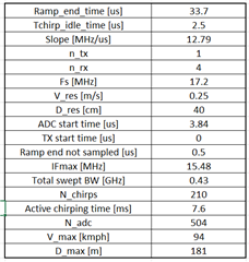
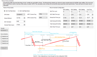
In the pictures below you have our configuration parameters, mmwave studio ramp timing calculatorand also mmwave sensing estimator.
Our configuration doesn't work for more than 208 chirps which is really strange. If we drastically lower number of samples per chirp it sometimes successes but we can not figure out some timing and memory limitations. As I understood the documentation, it says that 2.4Gbits/s throughput is available per chirp of 4rx data (600Mbits/s per Lane meaning per RX) so I think our configuration is lower than 2.4Gbits/s. Also suggestions for adc_start_time, idle_time and ramp_end_not_sampled time are taken into consideration and chosen above limits defined like a precaution (idle 2.5 instead of 2, adc start time 3.84 more than 99% settling time, ramp_end_not_sampled 0.5 instead of 0.3 etc.).
So, can anyone explain why this configuration won't work? We are using 12V 5A for power supply. Could possibly frames with higher number of chirps need more current (I saw 8A max)?
Is there some memory limitation on number of chirps? Is there some problem with having number of samples NOT 2^n form? Could you check throughput of our configuration, we calculate it in a way that system works in ping/pong manner so time needed for transfer of one chirp data (4RX) is ramp_end_time + chirp_idle_time. Do we understand correctly throughput limitation?

A lot of smaller questions but simple one to summarize is why should this configuration with 210 chirps wouldn't work.
Regards,
Predrag
