This thread has been locked.

If you have a related question, please click the "Ask a related question" button in the top right corner. The newly created question will be automatically linked to this question.

AWR1642BOOST: CCS v10.2 code

Part Number: AWR1642BOOST
Other Parts Discussed in Thread: AWR1642,

Hi,

I am using AWR1642BOOST with Code Composer Studio v10.2 to extract the Velocity, Range, Angle of the detected objects. I successfully connected AWR1642 with CCS by creating a New project using video.  I was not able to find any sample code / tutorial to proceed with CCS

Could you provide me with latest (CCS v 10.2) examples and tutorials on how to execute the code?

SDK Version: 3.5

System Configuration:

OS type: Ubuntu 18.04.5 LTS, 64 bit
Processor: AMD Ryzen 7 3800x 8 Core Processor x 16
GNOME : 3.28.2
GPU: GeForce GTX 1080 Ti

Thanks

Guru

  • Hi Guru,

    First, let me link a few resources:

    Getting stared with Code Composer Studio video

    Getting started view for CCS10.2

    These should give you a basic idea of what CCS does. For mmwave specific details, I would suggest these:

    The SDK 3.5 user guide's section 4. 4.: How to connect mmWave EVM to CCS using JTAG. The SDK user guide can be found here: C:\ti\mmwave_sdk_03_05_00_04\docs, or your equivalent SDK install location.

    This should give you an idea on how to run compiled binaries with CCS.

    To see an example of how code is compiled with CCS in the mmWave context, you would have to look at the TIREX labs for mmWave sensors. All of these labs are compiled with CCS. Their getting started/developer's guide contain step by step instructions on how to compile the lab. I would suggest looking at the medium range radar lab's developer guide's section: "Steps for Building from the Source Code and Run"

    For a more detailed theoretical look into how CCS debug works, see the debug section of the CCS documentation. This also goes into some debug functionalities provided by CCS.

    Regards,

    Aayush

  • Hi,

    Thanks for the reply

    To see an example of how code is compiled with CCS in the mmWave context, you would have to look at the TIREX labs for mmWave sensors. All of these labs are compiled with CCS. Their getting started/developer's guide contain step by step instructions on how to compile the lab. I would suggest looking at the medium range radar lab's developer guide's section: "Steps for Building from the Source Code and Run"

    I have tried with Industrial toolbox 4.6.0 in which user guide shows that CCS project can be imported into CCS software. But  unable to import CCS projects. Please refer images.


    How to import projects into CSS ?

    Thanks

    Guru

  • Hi Guru,

    Could you add the images here? I can't access  Google Drive easily from my work machine.

    Regards,

    Aayush

  • Hi,

    I'm not able to upload the image since there is no option to upload the image from the local storage. Kindly check with the link below for the corresponding images. The accessibility has been modified and you will be able to access it.

    https://drive.google.com/file/d/1LLjl3aYHaWyhfxElwWrzet9tbqS7gFml/view?usp=sharing

    https://drive.google.com/file/d/13bAMbrB0NpP-ftCPky4DbjF-KQSX7RCO/view?usp=sharing

    Thanks

    Guru.

  • Hi Guru,

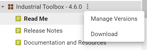
    I would suggest you download the entire toolbox itself. Refer to the image below to see how to download the toolbox.

    Regards,

    Aayush

  • Hi,

    Thanks for the reply

    I have installed and imported CCS project mmw_mss_16xx successfully. While proceeding with user guide  I was not able to build/ rebuild the project.

    Shows the following error:

    This project does not contain a buildable RTSC Configuration (.cfg) file. In order for it to build, this project must contain one RTSC Configuration file that is not excluded from build.

    And warning

    Product mmWave SDK v2.0.0.04 is not currently installed. A compatible version 3.5.0.04 will be used.

    I have installed mmwave_sdk_03_05_00_04 and this project has no config file regarding RTSC

    Q1. Is this ccs project compatable with only SDKv 2.0.0.04?

    Q2. Should I manually add RTSC config file?

    Q3. If so, how to add RTSC config and from where I can download such config?

    Thanks

    Guru

  • Hi Guru,

    Is this ccs project compatable with only SDKv 2.0.0.04?

    That's correct. The projectspecs for AWR1642 in this toolbox are for SDK2.0. There was a pretty significant delta between SDK2.0 and SDK3.0 mainly in the data path, and I'm afraid the demo isn't backwards compatible. I'm attaching projectspecs I created a while ago for AWR1642 OOB demo with SDK 3.5.0.4. With these, your SDK 3.5 OOB project should build seamlessly.

    The .cfg files you refer to are provided with all SDK components which use TI's SYS/BIOS operating system, OOB demo being one of them, so I'm not sure why you encountered that error. Nonetheless, the root cause was the incompatibility between the projectspecs you used and the SDK insallation.

    Also, internally, we don't compile SDK components through CCS. All SDK components can be built by using their corresponding makefiles. Compiling SDK using makefiles is pretty straightforward, you can have a look at the SDK user guide (here: <SDK_INSTALL_LOC>\docs\mmwave_sdk_user_guide.pdf) to see how.

    xwr16xx_mmw_demo_projectspecs.zip

    Regards,

    Aayush

  • Hi,

    Thanks of reply

    I have added xwr16xx_mmw_demo_projectspecs and imported into CCS.

    During build I received error (refer attached image)

    error #10247-D: creating output section "systemHeap" without a SECTIONS specification
    error #10010: errors encountered during linking; "xwr16xx_demo_mss.xer4f" not built
     
    >> Compilation failure
    makefile:171: recipe for target 'xwr16xx_demo_mss.xer4f' failed
    gmake[2]: *** [xwr16xx_demo_mss.xer4f] Error 1
    gmake[1]: *** [main-build] Error 2
    gmake: *** [all] Error 2
    makefile:167: recipe for target 'main-build' failed
    makefile:162: recipe for target 'all' failed

    Help me with this error ?

    Thanks

    Guru

  • Hi Guru,

    Sorry, I forgot to mention a couple of steps to use these projectspec files:

    1. You would need to place them in <SDK_INSTALL_LOC>\packages\ti\demo\xwr16xx\mmw

    2. You would need to build the DSS project before the MSS project.

    I think you encountered this error because you didn't follow step 1.

    The first restriction was actually due to  an oversight on my part in making the projectspecs. I'm attaching an updated version which could be imported from any location. You would still however need to build the DSS project first.

    xwr16xx_OOB_demo_projectspecs.zip

    Regards,

    Aayush

  • Hi

    Thanks for the reply

    I  have downloaded the above sent zip file (xwr16xx_OOB_demo_projectspecs.zip) and imported into CCS. I followed the steps during build of DSS project it shown me the following error

    "../objectdetection.c", line 71: fatal error #13: expected a file name

    Do I need to input a file?If so, could you lead me from here

    Thanks

    Guru

  • Hi Guru,

    Please try the files attached with this reply. Again, this was something I developed internally and not for immediate release, there were some customizations/issues with the projectspecs that weren't addressed.

    I have tried the files attached here with a vanilla installation of the SDK, and it works.

    If you want to know exactly what happened with the last projectspecs, they were missing the path to mmw_res.h file. This file comes with the SDK demo itself, and contains some information about EDMA utilization of the demo. This file is used by the datapath.

    I had made some changes internally to bypass this, hence it wasn't in the projectspecs I had sent you.

    2625.xwr16xx_OOB_demo_projectspecs.zip

    Regards,

    Aayush

  • Hi,

    Thanks a ton

    Successfully build both DSS followed by MSS.

    Still I could see only two files (.xer4f and demo_mss.bin) in debug folder of MSS, I need a .bin file to be flashed into board according to User guide of SDK, under section 3.

    And I have attached a screenshot took during build of MSS for your refernce

    Thanks

    Guru

  • Hi Guru,

    The JTAG debug binaries (.xer4f and .xe674) can also be used with CCS debug to run the demo. However, to get a image binary (.bin file), these files are combined and converted. This conversion is done with the help of a few .exe files available here: <SDK_INSTALL_PATH>\packages\scripts\ImageCreator. I am not sure if there are equivalent versions available for Linux. I would recommend you try this with a Windows installation.

    Regards,

    Aayush

  • Hi,

    Thanks for the reply.

    I have successfully build .bin file in linux using this following command in script folder of mmwave SDK 3.5

    ./generatedMetaImage.sh AWR16XX_mmw.bin /<debug path>/xwr16xx_demo_dss.xe674 /<debug_path>/xwr16xx_demo_mss.xer4f

    Which is been successfully flashed into sensor(AWR1642)

    But demo visualizer is not responding and sensor is not started.
    Can you please help me with execute the bin file in sensor.

    Thanks 

    Guru

  • Hi Guru,

    Can you run the demo with the pre built binaries? Did you ensure to put the EVM back in functional SOP mode after flashing and do a restart of the EVM?

    Regards,

    Aayush

  • Hi, 

    Thanks for the reply.

    Yes, I have run the demo with the pre build binaries. It's working correctly.

    SOP jumpers have been kept correctly while flashing.

    Am I missing anything else?

    Thanks

    Guru

  • Hi Guru,

    ./generatedMetaImage.sh AWR16XX_mmw.bin /<debug path>/xwr16xx_demo_dss.xe674 /<debug_path>/xwr16xx_demo_mss.xer4f

    I think your usage of this script is incorrect. The script call needs to look something like this: 

    generateMetaImage.sh <FLASHIMAGE> <SHMEM_ALLOC> <MSS_IMAGE_OUT> <BSS_IMAGE_BIN> <DSS_IMAGE_OUT>
     
    You can have a look at the comments in the script for more details.
    You missed SHMEM_ALLOC and BSS_IMAGE_BIN. You can use 0x00000006 as <SHMEM_ALLOC>. <BSS_IMAGE_BIN> is: <SDK_INSTALL_LOC>\firmware\radarss\xwr16xx_radarss_rprc.bin
    Regards,
    Aayush
  • Thanks for the reply

    I have built it and ran successfully. And I have a final question regarding range and velocity.
    Range, velocity are only visible in demo visualizer.

    I need them as values that can be accessed and printed using c programming.
    Could you please help me with this ?


    Thanks
    Guru

  • Hi Guru,

    The device data is exported in TLV message format detailed in the OOB demo's doxygen documentation. 

    To get meaningful values out of the data, two steps are involved:

    1. Parsing the binary TLV format data to a usable representation.

    2. Assigning appropriate units to the parsed output data. (The range, doppler data is not in SI units. Rather, the range and doppler bin index of the detected object is exported, which needs to be converted into meters or meters per second depending on the configuration you used)

    The demo visualizer does both, and it's source code can be accessed under Help->Download or clone visualizer.

    For step 1, I did write an experimental, untested, unreleased script to capture and parse the object data coming over UART to JSON. You can find that in the following thread:

    https://e2e.ti.com/support/sensors/f/sensors-forum/985107/awr1642boost-mmwave-demo-visualiser-captured-data

    This script parses data recorded over visualizer with its offered recording functionality.

    For step 2, you would have to either use the demo visualizer source code as reference, or try to map the indexes to SI units by looking at the OOB demo's source code. Here is a similar question I answered recently about how to figure out such mapping for the OOB demo:

    https://e2e.ti.com/support/sensors/f/sensors-forum/987753/awr1843-awr1843-doppler-index-into-velocity

    Regards,

    Aayush