Hello,
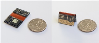
We have made a custom rigid flex board with IWR1843, please see picture below.
In this PCB revision we used LP87524-J as the PMIC, however we're facing issues when feeding the PMIC's VIN_B0/3 rails with low voltage, such as battery voltage in the range of 3.5V-4.1V.
The main issue is the 3.3V rail, as the PMIC requires input voltage to be at least +0.5V above the output voltage, the LP87524-J has one 3.3V rail that we don't use. We could have used it but then we will be out of specs and so we just put an external LDO for supplying 3.3V. We still include all the PMIC's recommended external components for the unused 3.3V rail, because we want to have the PGOOD indication as a reset source to the IWR1843. However, it seems that unused 3.3V rail is not stable with the recommended values in the datasheet, every current pulse drives the 3.3V by more than 0.1V upwards and the PGOOD (our reset) goes low.
We see that with added capacitance this helps solve the problem for 90% of the boards however there are 10% in which VCC is inherently a bit higher (assuming because of internal PMIC resistors / reference) and either I need more capacitance or even some bleed resistor.
Now, I'd like to avoid all that altogether in the next PCB revision. I thought to move to the LP87524P option, which has no 3.3V output. Instead, it has two 1V outputs. Assuming I can't just short them together, and as with the experience above, I'd also wouldn't want to leave any of them without load, I'm wondering what would be the best connection.
We have three rails consuming 1V in the mmWave sensor: VIN_13RF1, VIN_13RF2 and VOUT_PA (since we're working with 3 tx antennas, this is the recommended connection).
I was wondering if you could suggest:
1. First, just to make sure, none of these 3 rails are shorted internally (which may cause short on the two PMIC 1V rails), is this correct?
2. What is generally the current distribution in these 3 rails? how would you suggest to connect, i.e first 1V rail to VIN_13RF1 / VIN_13RF2 and the other rail dedicated to VOUT_PA? or other option?
3. I'd like your opinion about the LP87524J. Any quick fix to avoid the unused 3.3V providing PGOOD / reset going low? we don't need the 3.3V as we use external LDO for this, we just need to clear the reset issues as elegantly as possible.
Thanks in advance
Guy Shemesh
ePiccolo Engineering


