This thread has been locked.

If you have a related question, please click the "Ask a related question" button in the top right corner. The newly created question will be automatically linked to this question.

FDC2214EVM: FDC2214EVM : Can someone help me solve my problem?

Part Number: FDC2214EVM
Other Parts Discussed in Thread: FDC2114, FDC2214,

I made a hollow circle with a very yellow short copper wire and attached it to channel 2 as a single-ended sensor , as shown below.The circle is about 3cm in diameter.

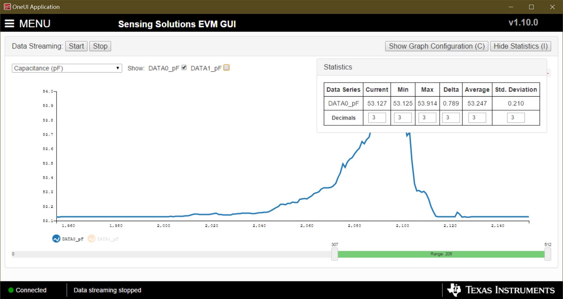
And I checked "Enable" of channel 2 in Sensing Solutions EVM GUI. I found some phenomena that I can't figure out.

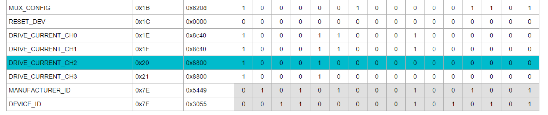
1. When I go to check the value of the registers, vaue of register "DRIVE_CURRENT_CH2"  is "0x8800" while values of register  "DRIVE_CURRENT_CH0" and register "DRIVE_CURRENT_CH1" are both "0x8c40". why are these registers' values  different? Does it influence  the sensor although the drive current is same?

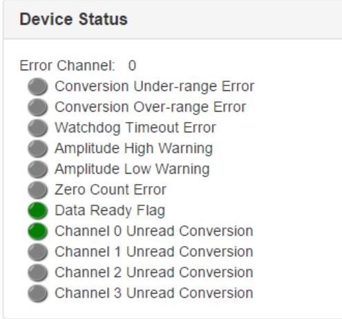
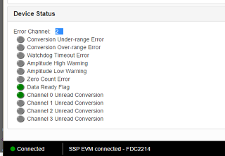
2.In the "Configuration" screen ,"Error channel: 2" is displayed below "Device Status" bar. Is there any error in channel 2?

   I can't find any information about this in the FDC2114 and FDC2214 EVM User’s Guide.Then, how to solve it?

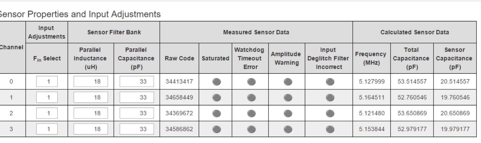
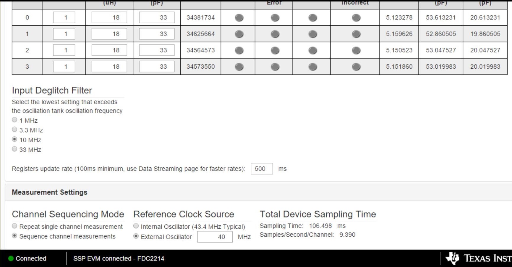
3.After I remove the copper circle from channel 2,the raw code of channel 2 is as same as  without removing it. How to explain it? And I find that channel 2 shows a parasitic capacitance of about 20 pF regardless of which sensor is connected or not. Is this correct?

4.I used sensor connected to channel 2 for some simple tests. I thought of my hand as a target object to approach the sensor and get some results. I let my hand to approach the sensor from about 10cm away, and when the distance reached about 4cm, the capacitance curve of the sensor began to increase visibly. According to the data getted from GUI, the maximum capacitance difference is about 15fF, and I don't make sure that it meet the SNR ? 

Regards.

  • Thank you for your inquiry and your interest in TI products.

    1. I checked the default register settings on my FDC2214 EVM, and channels 1-4 all have the same setting. 
      The register entries must have been revised.
    2. The FDC2214 sensor is based on a resonating LC circuit formed by 18uH on-board inductors and the capacitance of the sensor. The frequency of the tank circuit must be within 10kHz to 10MHz. The Q of the circuit - or its equivalent effective parallel resistance - coupled with the drive current, will determine the amplitude of the resulting sensor waveform. If the amplitude is too low or too high, it will generate an error. If the frequency is too high or two low, an error will result. This is probably what you are seeing. Please see the FDC2x1x Capacitive Sensing FAQs on this forum's landing page for more detailed information. The app notes shown in the section Inductive Sensing App Notes With Useful Info... may be helpful. 
    3. This does not sound correct. Please try disconnecting the EVM, closing the GUI, reconnecting the EVM and restarting the GUI.
    4. My guess is your wire sensor does not offer enough capacitance to allow the correct FDC resolution, possibly because of the factors mentioned in item 2. 

    Regards,
    John

  • Hi,John.Thank you for your reply.

    1. I reset this EVM ,however ,the default register settings is the same as what it is before I reset it. As shown below, the default values of channel 0 and 1 are 0x8c40 while the default values of channel 2 and 3 are 0x8800. 

    I checked the default register settings on my FDC2214 EVM, and channels 1-4 all have the same setting. 
    The register entries must have been revised.

    Why is this default value different from what you said?

    Which value should these registers be changed to? 0x8c40 or 0x8800?

    2.I discovered a new problem with the "Device Status".

    When I choose "Repeat single channel measurement" and check channel 0, "Error Channel:   0" appears below Device Status bar.

    When I check both channel 0 and 1,"Error Channel:   1" appears below Device Status bar.

    When I check  channel 0 , 1 and 2 ,"Error Channel:   2" appears below Device Status bar.

    When I check  all channels ,"Error Channel:   3" appears below Device Status bar.
    Why is it ? And I can't get more information about it .

    If the amplitude is too low or too high, it will generate an error. If the frequency is too high or two low, an error will result. This is probably what you are seeing.

    As shown above, "Amplitude high warning" and "Amplitude low warning" are grey.Does it mean the amplitude is not too high or too low? Which specific frequency is the frequency you said above ?What should I do to determine if the frequency is too high or too low?And I don't change other parameters in the software.
    3.

    Please try disconnecting the EVM, closing the GUI, reconnecting the EVM and restarting the GUI.

    I did it according to what you said.

    When I connect homemade sensor(seen above) to channel 2,sensor capacitance is about 20.65pF.

    After I disconnect it ,sensor capacitance is about 20.05pF.

    The capacitance difference is about 0.6pF. Is it  normal ?

    4. I'm sorry you did not understand the question that was meant for me.I want to figure out that when the target object starts to enter the detection range of the sensor, how much  the sensor capacitance should increase.

    In another word, when the capacitance of the sensor increases by how much, it can be considered that the target object begins to be detected by the sensor.

    Is this resolution?(I'm sorry I don't understand what it really is.) If what I say is resolution,can you tell me what the resolution of this EVM is?

    Regards.

    1. The most likely thing that happened was that a new register value was saved to the EVM.
    2. Please try probing the sensor circuit with a high impedance probe and noting if the measured signal falls within the range given in the data sheet. If the signal frequency is too high or too low, it could trigger the Unread error you are seeing.
    3. Your sensor is a little out-of-the-ordinary. I can't say if what you are reading is normal.
    4. The overall resolution will depend on not just the device and its settings, but also the sensor. 
      You will need to measure the resolution with your sensor and your desired device settings.
  • thanks for your reply.

    1.Do I need to revise the register value manually?If yes,which register should be changed and what should register value be ?

    2.I'm sorry I don't understand  what you mean. Could you explain that in more detail ? Millions of thanks.

    3.okay.

    4.How could I measure the resolution ? Could you please tell me more about way to measure it?

    regards.

  • You can revise the register manually, and will need to if you want to use non-default settings. The values should be based on your system requirements.

    It was probably wrong to use the word 'resolution' in my last reply. Apologies for that.
    You will have to work with your sensor and device settings to find what works for your application. 

  • Well, could you please tell me that when using default sensor connected to channel 0 or 1 ,how to measure the maximum distance that can sense? What is the change in frequency or calculated capacitance that means the sensor is sensing it?

  • The easiest way to determine the maximum distance is to:

    1. Note the output level on the GUI with no target near the sensor.
    2. Next, using a sample of the target material you wish to use, start with the target far away from the sensors that there is no change in the output from (1).
    3. Slowly move the target toward the sensor until you get a change from the value in (1).
      The amount of change that is needed to establish the maximum usable distance depends on your requirements, but 10% may be a useful baseline.
  • thank you for reply.

    The amount of change that is needed to establish the maximum usable distance depends on your requirements, but 10% may be a useful baseline.

    If the initial capacitance of the sensor is about 20.65pF, then the target object can only be considered at the maximum induction distance when the capacitance change value is about 2.065pF, i.e. the capacitance is about 22.7pF.
    Am I reading this correctly?

    regards.

  • Yes. That is what I was suggesting.

  • I did a simple experiment with one onboard sensor on the FDC2214EVM.
    The sensor's size is 20.9mm×13.9mm,which should be able to achieve proximity sensing  at distances greater than 17cm according to TI's datasheet.

    I used an aluminum sheet as the target object to approach the sensor (the area of the aluminum sheet is larger than the sensor), but even if I put the  sheet very close to the sensor (less than 1cm, but not touch the sensor), the maximum capacitance change shown by the Sensing Solution EVM GUI is only 0.789pF, which does not meet the requirement of 10% (i.e. about 2pF).

    Why is it?

  • It most likely is a function of your sensor and the device settings. 
    You will need to experiment with your device settings to get the results you are looking for.