This thread has been locked.

If you have a related question, please click the "Ask a related question" button in the top right corner. The newly created question will be automatically linked to this question.

TUSS4470: TUSS4470 - Driving 100W Transducer

Part Number: TUSS4470
Other Parts Discussed in Thread: BOOSTXL-TUSS4440, CSD88537ND, PGA460

Hi,

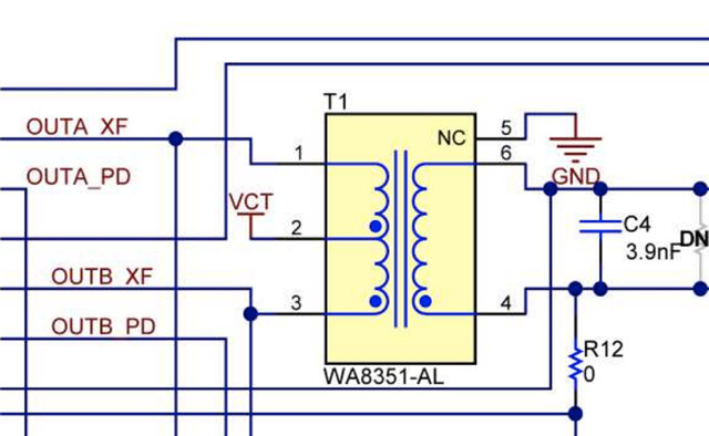
is there a circuit recommendation to drive the TUSS4470 with external mosfet/transformator to drive a 100W transducer?

The 12V battery voltage is available to connect to the circuit and i think i would have to use the internal mosfet to drive the external mosfet circuit right?

Because the direct drive mode will not be able to supply 8A output current using the internal mosfet right?

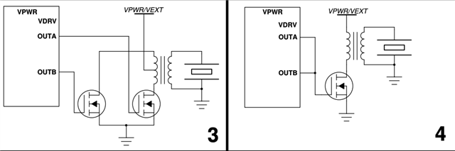
What would be the best approach then 3 or 4?

And what mosfet and transformator could i use to drive the transducer at 100W?

Bets regards,

Michael

  • Michael,

    Thank you for reaching out with your question.  For a reference with possible component options, please refer to BOOSTXL-TUSS4440 EVM.  The schematic and is available within the user's guide. 

    https://www.ti.com/lit/ug/slau822a/slau822a.pdf

    While the FETs are not installed, you should be able to find the components selected for that use in the Bill of Materials. You are right though that the output current of the direct drive mode cannot support the power you are looking to drive and therefore you will need to use the pre-drive mode.

    Whether you select method 3 or 4 will depend on the transformer you select.  Notice that in mode 3 a center tapped transformer has been selected.

    Thanks,

    Scott

  • Hi Scott,

    thank you for your answer. I saw the mosfet FDC8602 datasheet and it can only drain 1A current right?

    Would the CSD88537ND be an alternative together with 750317611 or  WA8351 transformer to handle 100W transducer

    or is there a better alternative?

    I dont understand the transformer circuit. On the datasheet from WA8351 it says that the transformer has 1:8.4 turns. Does it means if the current flows from primary side it should be the same current on the secondary side and voltage would be 8.4 times bigger? For example if the primary site VCT=12V and the H Bridge is driven 1A, would the current in secondary side be 1A and the voltage be (12* 8.4) v?

    If thats the case then P = (12 * 8.4)V * 1A = 100W right? Than the FDC8602 would be suitable. Please correct me if i am wrong.

    And one other question, what does the C4 capacitor do? Is it for the transducer resonant frequency adjustment?

    How do i know which value i should use?

    Best regards,

    Michael

  • Michael,

    Sorry for the short delay getting back to you.  I was out of office yesterday.

    The FDC8602 can handle a maximum of 1 A continuous current.  For pulsed current it can take up to 5A.  Still, this is lower than the target you had suggested, so another device might be more appropriate for your case.  It looks like CSD88537ND has lower Rds on than the FDC device and higher continuous current rating of 8A.  This seems like it should be a good candidate for your application.

    In any transformer, we must have a conservation of energy.  This means that when voltage is stepped up, that the current will proportionately scale down.  There is a discussion on the subject in the article here:

    www.ti.com/.../slup205.pdf

    Since TUSS4470 cannot drive the power needed for your transducer, we need the device to drive the FET gate so that we can source the energy from the supply.  If you need (12V * 8.4) * 1A in the secondary, then you will want to have (1 A *8.4 ) * 12 V in your primary, so your FET must be rated to handle 8.4 A.

    The capacitor C4 is there primarily to help with dissipation of ringing that can occur here.  If the ringing lasts too long, then it can be difficult to detect the echo for the ToF measurement.  At large distances, this is less of a problem. I would probably start with an empty placeholder here and then monitor the response.  If there is ringing here that exceeds the minimum expected ToF then you could add something here to help reduce that.

    Thanks,

    Scott

  • Hi Scott,

    thank you for your answer. 

    You are right the input energy should be the same as the output on the transformer. 

    I will try a custom PCB with the CSD88537ND mosfet.

    Will the 750317611 or  WA8351 be a good transformer for this application? I saw that both transformer are specially made for ultrasonic sensors, is because of the pulse frequency bandwidth?

    And last question just for understanding: Why are the transformers used anyway?  If they are just to increase the voltage or current, but the output power remains the same on the primary and secondary side. Wouldnt it be possible for the mosfet to drive the transducer directly?

    Best regards,

    Michael   

  • The transformer is there as many transducers require a higher voltage in order to operate.  If your supply voltage isn't sufficient to excite your transducer, then you need to step it up to something higher.

    The transformer does need to be able to operate with appropriate frequencies, but aside from the form factor on WA8351 and perhaps the ratio, I'm not sure on the history of what was configured specifically for ultrasound.

    Here's an E2E post with some more options you could explore.  These were verified to work with PGA460

    e2e.ti.com/.../pga460-air-coupled-ultrasonic-transducers-transformers-listing

    The key concern I have on any transformer would be the current rating.  If driving too much current through any inductance based device, it is possible that performance will degrade, or that worse the device may be damaged.  I would take extra care to ensure that the coil will hold up to the level of current you end up driving in your transducer.  

    Thanks,

    Scott